Wind energy is enjoying a tremendous lift because of stable U.S. policy as well as the global markets where targets reducing greenhouse gas emissions range from 20 percent to 30 percent over the next five years. However, the common driver that has served the industry best is the dramatic rise in turbine capacity factors that continue to move the needle in the reduction of the levelized cost of electricity (LCOE) for wind-generated power. It is well known that in just the past seven years, a 66 percent reduction in LCOE has been realized. While technology improvements in control systems, plant level system optimization, and reduced O&M costs have all contributed to lower LCOE, the single most relevant factor in this decline is a result of ever larger wind turbine blades optimized for low-wind class siting driving up turbine Capacity Factor (Cp).
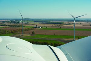
The growth in swept area of turbine rotors is not a new phenomenon. We have seen this trend for more than 20 years as the technology grew from modest sub-megawatt machines to equipment at utility scale that often exceeds 3.5 MW. However, what is new is the extraordinary extension of blade lengths that swing on comparatively small assets. Who would have imagined the growth of a rotor 70-meter diameter on a modest 1.5 MW machine to 125 meters on fundamentally the same fixed asset?
Growing opportunities
There is no practical end in sight, and combined with increasing hub-height, the opportunities to continue to grow blade length and rotor diameter remain on the rise as well. What does this all mean for the design and manufacturing engineering necessary to support this trend? Well, if one considers that blade root diameter remains largely fixed to maintain commonality of platform on these baseline hubs, drive trains, gear boxes, and generators, then a longer blade implies higher root (bending) moments and higher tip deflections. Transportation logistics limit maximum chord width in blade design, which in turn constrains the section properties. The trend in blade design is higher aspect ratio and low total disc solidity. Section properties are constrained with respect to geometry. This only further challenges tip deflection because there is simply no means of reducing tip deflection without increasing the mass of the spar cap or significantly increasing specific stiffness of the spar cap materials themselves.
Blade design and manufacturing processes have responded quickly to meet this challenge. The use of higher specific stiffness materials has been applied to create higher stiffness without significant increase in mass. We see a growing trend in the use of both “high modulus” glass (H-glass) and carbon fibers for blades spars. Just as importantly, it is the manner in which these advanced fibers are used that merits attention. Where traditional approaches have favored the lamination of spars using vacuum resin infusion methods, a new trend of laminating precured elements in the form of pultruded flat plate profiles has taken hold. The pultrusion of spar cap elements that are stacked and laminated to produce a tapered beam not only improves overall laminate quality (with elimination of porosity) but also creates the highest possible fiber volume fraction while ensuring the highest possible collimation (alignment) of fibers. This means more total contribution to axial stiffness and lowest cost for the direct application of reinforcements.
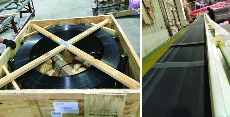
Laminated pultruded plates use the fiber in a format that includes no additional secondary conversion to a textile format while using very low labor content. This closes the gap between the cost of H-glass and carbon fiber reinforcements compared to the economical E-Glass fibers knitted or stitched into non-crimp fabrics (NCFs) traditionally used with infusion processing of wind-blade spars. It is likely that this move to pultruded profiles for wind-blade spars will continue as OEMs more broadly adopt this technology in the next generation of extended length blades.
Also, likely to drive this trend to high specific stiffness materials is the progress made in the processing of “low-cost” carbon fiber using industrial grade polyacrylonitrile (PAN) fibers from spun melt processes (as opposed to solution melt). Work from Oak Ridge National Laboratory in Knoxville, Tennessee, projects carbon fiber cost with intermediate modulus performance at costs projected well below $5 per pound in U.S. currency. Commercialization of this technology is underway by at least three different publicly announced licensees. Coupled with pultrusion processing, the combination of economics may very well result in parity with spars made from low-cost glass infused subcomponents. We all will welcome success on this front.
Higher root bending moments resulting from blade growth affects another significant blade design technology. The interface between the composite blade root and the hub is most often bridged by discrete mechanical fasteners in the form of metallic bolts. Traditional root design often employed a configuration of radially drilled holes to receive a root “nut” and an axially drilled hole to receive the root bolt. This combination known as a “tee-bolt (a.k.a, “IKEA joint”) has provided a low-cost satisfactory method to mate and secure wind blades to their hub. The reality of extended blade length and resulting blade moment has significantly increased bolt loads requiring more bolts to be installed around the fixed bolt circle diameter.
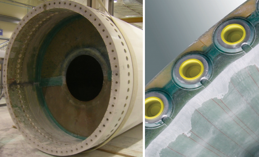
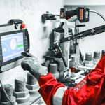
Bonded inserts resulting in higher total number of root bolts for blade to hub connection (Courtesy: SSP Technology A/S)
Many innovative solutions
The higher total bolt count all but obsoletes the traditional tee-bolt design and necessitates the use of bonded female threads in the form of root inserts. As with all technologies, there are many innovative solutions, and the result has been a run on the patent office as unique concepts are developed and deployed. An example of the value of this patented root technology is seen in the art of SSP, which only recently was acquired by Nordex, a significant turbine OEM.
Additionally, many other OEMs have shown through published IP their interest in adopting and protecting their root insert designs and methods with the expressed aim of increasing the number of bolts installed on a fixed bolt circle diameter.
The drive to higher Cp will not end with spars and roots. We know that greater hub heights will further increase Cp along with larger rotor diameters, and this, too, will further drive blade length. Transportation considerations will drive modular designs and field assembly along with novel trailers for trucking and rail cars for train transport. Indeed, the challenge for all those who manufacture turbine blades will be to increase agility and manage product change so OEMs can provide a family of blades to accommodate a variety of wind sites, hub heights, and maximize capacity factor. We look forward to this challenge because with it, comes great opportunity.