


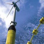
Accurate measurement is imperative to maintaining success in manufacturing wind turbine components. Poor-quality components result in extra costs and inconvenience for everyone involved. It’s important to always maintain the compliance of dimensional drawing requirements for individual pieces that make up a turbine. For example, when a gearbox is not manufactured properly it will potentially lead to premature failure of component gears, bearings, and perhaps even the housing itself.
Meeting Design Criteria
If there is a problem due to inaccurate measuring, it can easily cost $200,000 just to bring a crane out to a tower location before any work is done. A gearbox rebuild can cost upwards of $100,000, and generator rebuilds can cost around $25,000. It is not uncommon to have a three month lead time to get a crane capable of servicing these larger wind turbines, resulting in the loss of revenue for a full fiscal quarter. Any unplanned maintenance in these areas can affect the reputation of the wind farm, the company whose logo is on the nacelle, and potentially the entire wind industry.
So how do you make sure that gears, bearing races, housings, and other machined subcomponents meet design criteria? The easy answer is to measure them, but this is easier said than done for a couple of reasons. Let’s start by looking at how the tolerances commonly specified on these parts are often quite challenging. Many of the piece parts are very large, and many companies simply do not have gages of sufficient size or accuracy to make the necessary measurements. It’s very common to underestimate the repeatability requirements of the gage that is being considered for inspection. Typically, when you have a manufacturing tolerance, you would like your gaging variation to be less than 10 percent of the manufacturing tolerance. This means that the gaging system must have an average repeatability of less than 4 percent of the part tolerance.
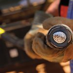
One example would be that if the part drawing shows a dimension with a 0.001 inch tolerance, the gaging system must exhibit an average repeatability within 0.000033 inches (0.025 mm would require an average repeatability of 0.0008 mm). This criteria is even more crucial when producing parts for the wind turbine industry, because the volumes are not typically large enough to do machine tool offsets based on statistical sample sets. When measuring one part, the data must be correct and trusted (Figure 1).
There must be both accuracy and repeatability in your gaging systems to ensure correct actionable data. If you measure a part a second time and get a different result, then your gaging strategy should be in question. Specifics that can influence the results of the measuring machine include the machine size, the weight capacity, the thermal environment, and vibration sources.
Unique Measurements
Sometimes, bigger really is better. Carl Zeiss manufactures many unique models of coordinate measuring machines (CMMs) that address different measurement problems. Among these are systems specifically designed to measure large wind turbine parts. Carl Zeiss has built and delivered high precision gantry measuring systems with measurement volumes up to 5 meters wide, 11 meters long, and 3.5 meters high. As the measurement systems become larger it is necessary to account for environment factors that may be negligible in smaller sized systems.
To ensure the best accuracy Carl Zeiss has chosen to use steel structural components on these larger high-accuracy machines, similar to most machine tools. The structure was designed using the latest finite element design tools available. Other materials, especially for larger machines, will have the tendency to increase variability. For example, when used in these large-scale machines granite is subject to swelling with humidity changes. This can affect the bearing relationships, requiring greater bearing offsets that result in measurement variation. Another adverse characteristic of the large-scale granite construction is that granite has very low thermal conductivity. When there is a change in the thermal gradient in a facility it will result in a bowing of the granite member. Over the long reaches of the CMM, this translates into significant potential measurement error. Carl Zeiss has carefully considered these environmental impacts in the design of these coordinate measuring machines.
How do you know the system accuracy is sufficient? There are some pretty good standards that specifically address this topic. ISO 10360 covers CMM measurement accuracy quite well. The difficulty is that some manufacturers may be more aggressive with their accuracy statements than others, making it difficult to use this as a clear differentiation value. Note that the accuracy specification only applies within the environmental specifications of the supplier. These specifications are usually footnoted, indicating that the tests are done with very short styli. Another point to consider is that the uncertainty of an indexing probe device is not considered in this statement.
The chart shown in Figure 2 is an example of repeated measurements of a traceable artifact on a large Zeiss MMZ G gantry machine. The red lines indicate the limits, and the small plus (+) marks indicate multiple measurements of the reference standard.
Testing the Technology
There is a better way to ensure that you’re getting the right machine. As previously mentioned, in order for a gage to produce meaningful results they must be repeatable. By asking the prospective suppliers to perform a Gage Repeatability and Reproducibility (GR&R) study you will begin to see the differences in the proposed systems. This test ties all of the pieces together. It requires the use of probe configurations necessary to measure your parts. The test will show whether the system can reproduce the measurement results from one inspection to the next. Otherwise the data from the gage is meaningless.
To learn more about GR&R studies, the Automotive Industry Action Group (AIAG) Web site—www.aiag.org—and Measurement Systems Analysis (MSA) manual are good sources.
Some manufacturers will discourage GR&R tests. This should definitely be considered a red flag. Why would they discourage the opportunity to show the capability of their machine to measure specific parts? One argument is that the test ideally requires the use of 10 different parts. For a variety of reasons this can be difficult to accomplish with large, low-volume parts. Smaller subsets of parts are also acceptable. As a minimum alternative, send a single part and have the prospective vendor inspect some critical dimensions. Then remove the part from the gage, reload the workpiece, and then rerun the inspection cycle.
This should be done approximately 10 times to review the range of measurement results.
Mathematically, the average range of measurement results should be less than 4-5 percent of the part tolerance to ensure you are not using over 10 percent of the production tolerance; with an 8-10 percent range you can expect a 20 percent GR&R. Figure 3
Yet another key advantage of the Zeiss CMM is the choice of sensor technology only available from Carl Zeiss. For larger components it is often necessary to acquire accurate data from features located a long distance from the sensor. The Zeiss VAST scanning sensor is able to take single points or scan surfaces using long probes. Through the use of patented force generators within the probe sensor it is possible to do this with the highest accuracy and repeatability. The sensors are critical to achieving the repeatable measurement results. The sensor contribution to measurement uncertainty and variability is limited in the ISO 10360 tests.
Alternatively, there are instances where an indexing probe system is beneficial. For this case Carl Zeiss offers the best combination; an indexing and scanning sensor. The VAST XXT sensor mounted to the indexing RDS head can take single points, scan the part, and index the sensor in 2.5-degree increments for ultimate access to geometry. An example where the RDS might be beneficial would be the inspection of a turbine hub. Specific inspection needs will dictate the sensor appropriate for the job.
Software Solutions
Software allows you to get the most from your coordinate measuring machine. The Zeiss CALYPSO®-based software has a user-friendly platform that provides the user with many metrology tools. This CAD-based software has tools to measure everything from gearboxes to bearing races, ring gears to pinions, and the ability to do profile measurements of turbine blades.
There are many features within the software to help the user focus on quality control rather than software manipulation. For example, when doing a GDT evaluation the user enters the data as it appears in the GDT control frame, referencing the pertinent datums as necessary. The software will create the necessary coordinate reference frames for the analysis. There are even tools to increase inspection throughput, graphical output options, and much more.
When a fly lands on a railroad track, does it bend? While this may be an extreme example, the theoretical answer is yes. With this thought in mind, a proper foundation must be considered when installing a gantry machine. Even a concrete foundation will bend when weight is applied to it. Since a gantry machine is usually built on a foundation, consideration must be given to the weight of parts being loaded, fixtures, and even the loading mechanism. All these components have the potential to cause the machine bed (the foundation) to bend. When you purchase a machine from Carl Zeiss we will provide recommended foundation drawings for your specific set of circumstances.
Another thing to take into consideration is that vibration in a plant can affect measuring machines. When the foundation is designed to accommodate the needed weight, Carl Zeiss will include the recommended vibration isolation system. Typically, there are three possibilites: 1) a passive system with a foam type of lining around the rebar reinforced concrete block; 2) a spring isolated system, and; 3) a pneumatic damping system. The soil conditions at your installation site, coupled with the prevalent vibrations, will dictate the system that is necessary. Any measuring machine that is installed without consideration of the prevalent vibrations will produce questionable results.
Conclusion
The large turbine wind energy business is a high-dollar business. In recent years, much of the warranty repair has been covered by the OEM suppliers of turbines. In the near future many of these earlier installations—within the past five years—will have expired warranties, and the burden of paying for the unscheduled repairs will fall on the wind farm owner. Whether the cost is covered under warranty or later by the wind farm, in all cases the costs come back to the consumer.
When manufacturing components for these wind turbines, take the time to review your inspection strategy in some detail. The points discussed in this article apply to other gaging systems, just as they do for coordinate measuring machines.


