


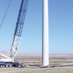
Mechanical failure in wind turbines presents unique challenges for operations and maintenance. Unlike traditional rotating equipment assets in other power generation plants, wind turbine assets sit on top of a tower 90m in the air. We do not have the luxury of performing maintenance tasks on solid ground. Tools and replacement parts must be brought up to the work site, and if you forget a tool or a part it’s not as easy as traveling back to the shop to retrieve it. It is critical to be able to prevent mechanical failure in a wind turbine whenever possible.
We see from the chart in Figure 1 that 60 percent of wind turbine downtime is related to drive train failure: gearbox, generator, main shaft, and their associated bearings. We also know from industry studies that misalignment of rotating shafts is responsible for more than half of all bearing failures.
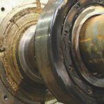
Precision shaft alignment is the process of aligning the centerline of the shafts of one or more rotating machines. When the shaft centerlines are co-linear they can turn freely, and the external forces that destroy key components of the system—bearings, seals, couplings, rotors—will be mitigated. Misalignment will most affect the main bearings in the gearbox and generator. Left unattended for too long, it will destroy the bearings and then go to work on other components down the line on the shaft such as seals and rotors, etc. Precision alignment at install and periodic checks can help prevent component failure, uptower repairs and catastrophic failure. A bearing failure uptower can cost $10,000-$15,000 to fix. Catastrophic failure can cost an estimated $260,000.00. A good alignment program can prevent these problems before they even start. There are various tools for alignment, some better than others. Consider these options:
Straight-edge mechanical tools
• Not a precision alignment
• Subject to gross interpretation of the user
Dial indicators
• Difficult to learn proper alignment method
• Time consuming process for the inexperienced
• Dials must be mounted on the shafts
• Shafts have to be able to turn to align with dials
• Can be subject to interpretation by user
Laser alignment tool
• Learning curve is short
• Very precise, even for an inexperienced user
• Many mounting options for different turbines
• Shafts do not necessarily have to turn
• No interpretation by the user, the data is the data
Precision alignment means you are using a laser alignment kit or dial indicators. A straight edge is not a precision alignment tool. Lasers have many advantages over dial indicators. Dials are hard to teach and learn. Until you have mastered the art of dial indicators, they can be very frustrating and time consuming. Lasers are a fast, easy, and accurate method of alignment. When you are performing alignment in a wind turbine there are a number of issues to consider.
Safety First
First and foremost is safety. Laser alignment tools must be mounted in such a way that they will not be able to come in contact with techs if the turbine brakes give way. Turning the shafts is critical to performing a precision alignment and O&M teams have to be aware under what conditions they can work uptower when the blades will be turned. The requirement to perform a measurement without turning the shaft is becoming more predominant. Figure 2
A sudden strong gust of wind can catch the maintenance team off guard and cause the shaft to spin freely as the brakes are being released for the alignment process. Some turbine manufacturers have developed solutions for alignment that do not require the gearbox to turn. This requires special fixtures and the coupling needs to be removed to perform the alignment. It is, however, the safest way to perform an alignment in a wind turbine. Know the guidelines that your turbine OEM has set for uptower alignment—maximum wind speed, direction the turbine should face, can the shaft covers be off or on, should the coupling be removed—make sure your maintenance teams are safety trained.
Mounting Laser Alignment Tools
In many cases we can’t mount with traditional chains and brackets on the gearbox shaft. This leaves us with the decision of where to mount the measuring (S-Unit) with a magnet. First, decide if you want to mount on the brake disc or the mounting flange for the coupler. Look for a place as close down by the shaft as possible. Check for clearance of the brake caliper.
Once you decide where to mount, check the measurement two or three times to make sure it repeats. On some turbines we have found that some components will shift when the brake is engaged. Mounting close to the shaft will minimize the effect. If your results are not repeating, look for an alternative spot to mount and re-test. If they do repeat, you have found a good solution.
Frequency of Alignment
The second consideration is deciding how often the turbine needs to be aligned. Many turbine OEMs have set requirements for turbine alignment intervals. Some OEMs only align prior to shipment from the manufacturing facility, some align when the turbine arrives “in-country,” and some align when the turbine is installed on the tower. Some do all three. It is never a bad idea to check turbine alignment. A precision alignment check should be included in your intervals of preventative maintenance. A quick check when the alignment is not scheduled to be performed can be done fairly quickly. Once you have determined that alignment is required, you can schedule it in your maintenance plan.
High-speed shafts should always be aligned during generator or gearbox change outs. Best practice says we should come back in three or so months and re-check the alignment. Again, this depends on the turbine manufacturer and their recommendations. Figure 3
Tolerances
Another important consideration is alignment tolerances. Alignment tolerances define how much misalignment is acceptable for a given model of turbine. Many turbine OEMs have established alignment tolerances for their equipment. If you don’t know the manufacturer’s tolerances, or they are not supplied, tolerance charts are available based on speed of rotation.
Dynamic Movement
The last consideration we will talk about in this article is dynamic movement. Dynamic movement is caused when the brake is released and the hub and blades turn freely. The weight and turning forces can cause the gearbox to move slightly, even imperceptibly to the human eye, and cause misalignment. You should consult your turbine manufacturer to find out if dynamic movement is present in their turbines, if they know how much it moves, and whether or not it is critical. In some cases the coupling can offset the movement when the shafts are aligned within tolerance. Once you know the amount of movement, you can add those calculations to your alignment tool. When compensating for dynamic movement, you will actually misalign the gearbox and generator at rest so that when it’s running the machines will move into alignment.
Lasers are also used in the wind industry as a valuable tool for measuring flanges on wind tower and blade root flanges. Flatness and taper measurements help ensure that these components will fit together properly during construction.
Precision alignment is a vital first step to prevent mechanical failure in wind turbines. Regardless of whether alignment is performed by the OEM, your O&M contractor, or your own O&M team, good tools and training are not optional. Remember that an ounce of prevention equals a pound of cure, lessening the chance for catastrophic machine failure uptower.
Features and Options
In addition to the design characteristics discussed, there are a number of other considerations or desirable features you should consider when building your wind farm grounding transformers.
First, advise the supplier whether you need a compartmental pad-mount transformer with integral tamper-proof compartment or substation design. Also consider whether the grounding transformer will be located outdoors or indoors, since even outdoor units need special attention when placed near other structures. Select the proper fluid type for the particular application—options include mineral oil, silicone, and Envirotemp® FR3™ fluid, a natural ester-based fluid with exceptional fire-resistant properties and favorable environmental attributes. Consider connectivity choices, and select the best one for the site. Options vary from dead front, live front, and spade terminals. Terminal location can be under a cover or on a sidewall, exposed or enclosed. In addition, temperature rise is assumed to be 65°C, so adjust design if necessary.
Consider site elevation or any special environmental concerns, and use special paint as required. Last, consider neutral ground resistors. The rated voltage of the NGR should be equal to the grounding transformer’s line to ground voltage. The current rating and duration should match the grounding transformer ratings. Remember to set the current rating high enough to be above the cable charging current and grounding transformer magnetizing current.


