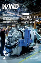
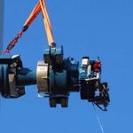
Cost effective condition management is one of the key ways to optimize the overall drivetrain performance and successfully achieve the estimated energy production in wind turbine generators. Wind turbine gears are exposed to extreme changes, both in terms of load and environmental circumstances. A drivetrain failure can mean prolonged down-time and very expensive major component repairs or replacement work. Therefore, it is essential to develop condition monitoring systems and analyzing methods that are truly comprehensive and relevant to the operating system.
Few condition monitoring systems have been developed specifically for wind turbine drivetrains. It is critical that these systems incorporate precise measuring instruments and highly automated analyzing tools. One single service engineer must be able to accurately provide information about each possible upcoming failure based on the available instruments and analyzing tools while closely monitoring hundreds of wind turbines. The most challenging components to monitor are the slow rotating machine parts in the drivetrain.
Traditional condition monitoring systems focus mainly on measuring vibrations from rotating components. For proactive results it is no longer sufficient to simply perform vibration analysis. This needs to be done in combination with oil condition and particle contamination analysis.
Proactive Versus Reactive Maintenance Strategies in Mixed Generation Grids
Electrical power generation is a critical resource and is managed and regulated by many federal organizations like NERC, FERC, and independent grid-system operators to ensure supply and demand management, optimal power quality, and uninterrupted supply. With many new sources of power generation being added to grids coming from wind and other renewable plants, effective management of generation forecasting by asset owners is critical. Nuclear asset operators are required to maintain detailed plans for asset monitoring, predictive maintenance, and long term maintenance plans. First quartile performing thermal asset owners also have well developed strategies to analyze data and plan maintenance activities into future planned maintenance outages. Thermal asset operators do have an advantage over renewable asset operators: location of generating assets. There is a large disparity in physical layout and original equipment instrumentation between traditional thermal power generation assets and renewable assets. Thermal assets are housed most commonly in a cluster of buildings and structures located more conveniently in a well-defined area and sub-systems are normally enclosed from the elements. In many cases, wind plants can stretch over thousands of acres/hectares and have hundreds of individual generating assets in one location. Given this more challenging plant layout and associated terrain based and seasonal access challenges, it is critical for owners of wind power generating assets to secure instrumentation to monitor “critical to failure” operational performance data and create proactive or predictive maintenance strategies to control costs of operation, optimize capacity factor, and generation revenue and provide accurate day-ahead generation bids to their grid operators. Wind generating asset operators seeking first quartile cost per megawatt and revenue optimization must incorporate not only hardware and software to collect data and stream it to a central location, but they must also have the necessary resources to trend and analyze this data. More importantly, the data must be converted from strictly technical form to more digestible presentation quality to facilitate dialogue and quick action when required.
The Challenge
More often than not, the level of accuracy and cost effectiveness comes in to play when condition management of wind turbine gears is considered. The continuous surveillance of a wind turbine gear fleet must be automated and optimized because one analyst must be able to monitor hundreds of systems and, at the same time, every failure has to be found. A wind turbine drivetrain can face several different failure modes, which require extensive and reliable instrumentation.
The combination of oil metal contamination and vibration analysis has been previously studied on machines with high rotation speeds. However, there are many challenges in monitoring machines with low rotational frequencies and especially those with intermediate speed gears. Low rotation frequency demands a relatively lengthy measuring time, which can be very challenging due to limited memory of the measuring device. It is difficult to achieve a proper time domain signal from a wind turbine where the rotation frequency varies during the measurement. Varying load and rotation frequency is problematic when calculating the Fourier transform as regular impacts do not show up clearly in the spectrum. With low rotation speeds the energy of impacts is low and therefore difficult to differentiate from the background noise of the vibration spectrum.
Oil contamination can provide valuable information about the existence of a failure but it does not say anything about the root cause. This is why we need a combination of oil contamination and vibration analysis. With low rotation frequencies, vibration levels do not rise above alarm limits but do provide valuable information about the root cause of a failure when that failure is initially detected with oil contamination surveillance.
Hardware
In the following case, the condition of the various gears within the gearbox is monitored using the Moventas condition management system (CMaS). This is a remote monitoring system specifically designed for wind turbine gears. CMaS is developed to monitor a large number of wind turbine gears very effectively by using sophisticated analyzing methods, algorithms, and intelligent sensors. These sensors are used to recognize possible damage to gears and other mechanical components in advance, before they start to affect and interfere with the turbine operations. When the sensor has processed and analyzed the data, it is then transferred to the CMaS main unit. Data transfer is conducted over a field bus. This means that in a normal operation mode, only key parameters are transferred. Spectrum and time domain data is also transferred regularly, but daily analyses are based on monitoring key parameters. When something outside the norm occurs, more-detailed data and raw signals are transferred. It is very important to successfully transfer key figures without losing any information. When daily monitoring is based on the analysis of key figures, monitoring is extremely cost effective.
In this particular case, the monitoring system has three Moventas intelligent vibration sensors (IVS-20), which all measure the spectrums, time domains, and key values in all three directions. Also included is a GasTOPS MetalSCAN full flow oil particle counter and other sensors for measuring temperatures and oil quality. Because wind turbine nacelles are a dynamic environment and have limited access for maintenance and troubleshooting, the connections between sensors and signal processing units must be durable and reliable to ensure maximum equipment up availability. Every nacelle and drive train has a specifically engineered configuration of sensor locations, cable routings, and processing units. Heavy duty, signal grade cabling is used to connect all devices. Connections at the processing units for oil and vibration data are heavy duty mil-spec components. Uninterrupted transmission of data is achieved through the use of mobile broadband technology. Mobile broadband SIM cards are employed to transmit data to surveillance centers. The use of mobile broadband also avoids any potential conflicts with access to turbine controller fiber communication access, and prevents the possibility of compliance issues with regulations pertaining to power generation cyber security. The flexibility of the CMaS unit does allow users the option to between broadband connectivity and their own turbine level fiber connection to fit their surveillance and data collection needs.
Analysis Methods
Daily monitoring routines (Figure 1) consist of checking each instance where the alarm has exceeding the alarm limit in every gear that is monitored. If abnormal behavior is found, a closer inspection is performed to check for patterns and trends of those measurements. Spectrum and time domain analysis are used for finding the root cause of a possible failure.
Intermediate Speed Gear
This example will concentrate on remote monitoring of a medium speed gearbox (Figure 2), having one planetary gear and one helical stage gear. The ratio of this gearbox is 1:28 and the nominal rotation speed of the output shaft is 464 RPM.
Case Study: Broken Tooth in Intermediate Speed Gear
At the beginning of December 2011, an unexpected rise in oil particles was detected with alarm limit monitoring (Figure 3). At the same time, there was no change in overall vibration levels or bearing temperatures (Figure 4).
Closer analysis of vibration spectrums indicated that there was a possible failure in the intermediate speed gear. This can be seen in the velocity spectrum (Figure 5), where there are side bands on both sides of the rotation frequency of the medium stage.
This provided the first clue that there was a failure in the intermediate stage, which was verified by analyzing the time domain signal where there were clear hits on the spectrum (Figure 6).
As soon as the root cause of this failure was identified, the client was immediately informed and a Moventas’ Field Service Engineer was dispatched to make a visual inspection of the gear. During the visual inspection, a fractured tooth was found on the intermediate speed gear. The tooth was not yet broken, but it was cracked (Figure 7).
Conclusions
In this case, a failure would not have been found if vibration analysis was the only option in the condition monitoring system because the vibration levels remained steady despite the failure. Nevertheless, the root cause of the failure would be impossible to find without vibration measurements and spectrum and time domain analysis.
For more information, visit www.moventas.com.


