


More than 80 percent of the ocean resource potential is in deep water. That is ideal for floating offshore wind power. This power is located high up for strong and consistent wind. The proven spar buoy will allow offshore wind to exploit these inexhaustible wind resources. Exponential growth in floating, deep water, far-out offshore wind is happening now worldwide. This spar buoys’ large potential, in the near term, is in Europe, Asia, and the Americas. It is the next big wave of renewable energy. The concrete spar buoy (CSB) will provide the potential for increase standardization in concrete floating turbine foundations throughout the world. The CSP will be a valuable floating foundation component in offshore wind.
European spar buoy construction and deployment
To date, the successful spar buoy in European waters is manufactured in steel. With a diameter of 49 feet and a length of 295 feet, there are only one or two plants that large enough with the crane capacity, height, and length to produce it. At approximately 8,000 tons, it is difficult to move to nearby water. Here, it is lifted with high capacity cranes on to a specially designed ship. At its destination, the ship is designed to take on water until the spar buoy floats free. After a horizontal tow out to sufficient water depth, it is upended with controlled water ballast placement.
At this stage, the permanent ballast is placed from a hopper barge. Next, with two of the largest floating cranes in any one country, the fully assembled wind turbine is lifted off the harbor’s nearby quay and towed out to the spar buoy. After placement on the spar buoy and the temporary ballast water continues to be pumped out, it is then ready for tow out to the wind farm.
Concrete spar buoy concept
To date, no one has designed a concrete spar buoy that has been constructed and deployed. To highlight some of the problems, it not always the design, but the constructability or a poor choice of materials.
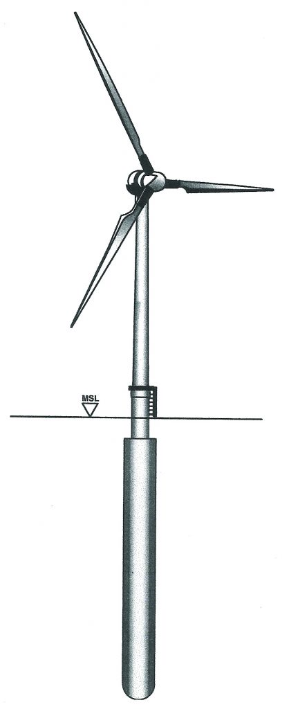
First, there is no need for a plant to produce the spar buoy or its turbine mast components. The spar buoy will be constructed in a dry dock and the mast components at a quay in the same harbor. The crew’s skill requirements can come from local trades. The spar buoy, after float out from the dry dock, will be towed horizontally to a deployment way point. This is a site that has sufficient depth to invert the spa buoy to vertical position with water ballast. An ocean-going deck badge will be waiting at the way-point site to install the fixed ballast off its one end and install all the wind-turbine components off the other.
This is accomplished by a heavy lift company out of Europe, where its crane sets and climbs the mast sections it is setting. It then sets the nacelle and blades. For the heavier 10- and 12-MW turbines, two cranes will be required, climbing the concrete mast sections on the 3 and 9 o’clock sides.
Spar buoy construction
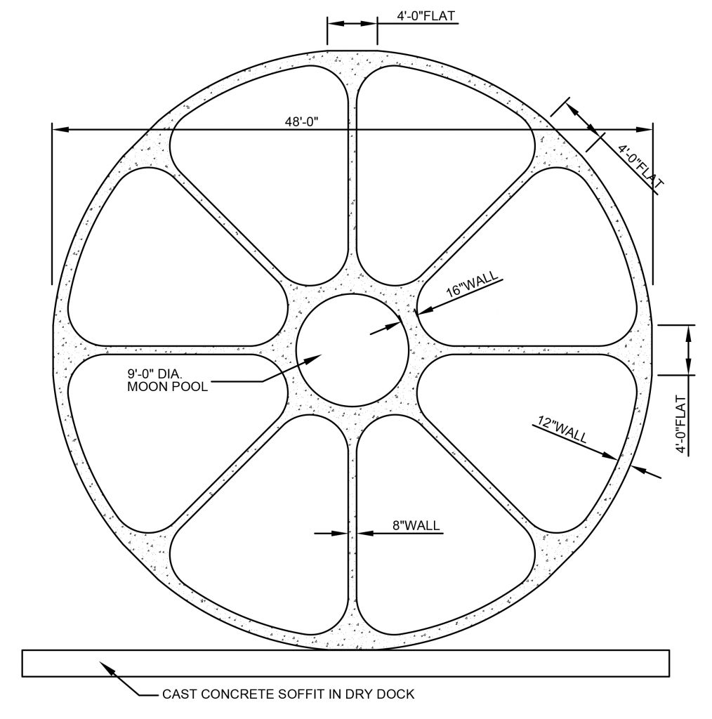
The concept for constructability was developed by adding eight four-foot flats (like a polygon) to the circular shape. This, in turn, developed an efficient construction formwork and sequence. This sequence required a balance of well-designed crane placed formwork, rebar, and concrete mix design, as well as addressing the safety issues in handling each. A dry dock will be required to build the CSB, of which there are many with enough depth and width to build two at a time. The first operation will be to pour a waste concrete soffit. This will act as both the parting surface for the float out of the completed CSB and the non-formwork casting surface of the bottom four-foot increment of the eight-sided octagon. All of the formwork components will have permanent hand rails and walkways built in as part of its design.
The first formwork component to be set will be the spar bottom or end plate. This form is in two parts: a 24-foot-deep by 48-foot-wide bottom half and top half. It is both the casting form for the spars’ bottom plate and support for the void forms in the first 25-foot long section of the spar. This section has two half bottom sections that are 24 feet, 4 inches deep and 25-foot-long right and left sections and four collapsible void forms with a void form support. The void forms are placed with a crane-handled balanced pick caddy.
Before the void forms are placed on the rodbuster, the crew will place and tie the preformed and pre-tied rebar skeleton. Next, the concrete placing, vibrator, and finishing crew will pour the concrete special mix design. The following day, the same procedure will take place on the top 23 feet, 8 inches of the spar buoy. This is a capsulated view of the construction.
Andy Filak)
Materials for the spar buoy and turbine mast components
The revolution in materials is the basis of this new concept. In existing marina concrete structures, the greatest threat is water, either fresh or salt. Through time, water penetrates into concrete through unseen cracks and the natural porosity and rusts the rebar skeleton. Even protected rebar has coating failures and deterioration that eventually causes the steel to fail.
Seawater also directly attacks the chemistry of ordinary Portland cement (OPC), causing rapid failure. What causes the OPC binder to fail at sea is the high percentage of calcium compounds (approximately 79 percent) that comes under attack by the sulphur compounds in seawater. This rots the concrete. The binder, in a concrete mix design, can occupy up to 20 percent of the mass of the concrete. Replacing the OPC in the concrete mix design with a geopolymer binder will foil this degradation scenario by minimizing the calcium compound in its chemical composition.
The geopolymer cement binder is made up of four inexpensive and widely available components: type 2 fly ash, fresh water, waterglass (sodium-silicate), and lye (sodium hydroxide). With the type 2 slag fly ash, the binder can have as little as 2 percent calcium, producing a saltwater-resistant material. Geopolymer cement binders are used commercially elsewhere in the world due to their superior performance to OPC binders. In general, these cements are stronger and both fireproof and waterproof. They bond well to most materials, have minimal expansion or contraction, are formable, and are resistant to salt, acids, and alkalis. The production process for producing geopolymers has an approximately 80 percent smaller carbon footprint than OPC.
To replace the steel rebar, a nonmetallic bar made from readily available basalt is used for reinforcement. Basalt stone (the generic term for solidified volcanic rock) is found all over the Earth and is a key component enabling the hundred-year durability of the polygon-16 spar buoy structure. The basalt stone, when heated to a temperature of 1,800 degrees, turns to a liquid that is run through a palladium die that produces soft flexible threads.
The threads are laid in parallel and locked together with an epoxy, producing basalt rebar — a water proof, chemical-resistant, fireproof material with a tensile strength several times stronger than steel. The geopolymer binder in the concrete binds to the basalt rebar on a chemical level in addition to the mechanical bond. The basalt bar is extremely light and also fairly flexible, lending to easy placement in the structure. Cut basalt fiber additives, much like nylon fiber, also are used in the mix design for added strength. The substructure will have a minimum of a 100-year life due to the low porosity, high strength, and cure technology found in the geopolymer binder in the concrete mix design.
Concrete mix design and placement
The key to the constructability of the CSB is the mix design. It has to be efficient to wet out and bind to the rebar with no air pockets. Part of this will be achieved through the discipline of the vibration crew. The other is the mix design itself. Geopolymer cement (the paste) has a high viscosity. To achieve its workability, its placement will need super-plasticizers. All are now designed for OPC binders. New hybrid super-plasticizers have been designed for geopolymer cement (binder) using rice husk and an alkaline that makes it possible to achieve the viscosity for placing the mix into the formwork.
The geopolymer cement (binder) will make up 20 percent of the mix. The rest will be measured granite saw dust as a replacement for the silica sand. This will have beneficial effects on the composite strength, split tensile strength, as well as the modulus of elasticity. The specific gravity of the silica sand is 2.83 whereas the granite is 2.65 to 2.85. The preference for granite is its strength and porosity, which is 0.25 percent. The porosity of the silica sand is 25 to 30 percent and holds unwanted water in the mix design. The other aggregates will be fine (1/4”) cut basalt fiber (stone) and crushed granite (3/16”). This mix design can be fine-tuned to achieve high strength and density.
The estimated time to construct one complete CPSB is estimated at 102 days and down line at 68 days. This time frame is based on fabricating two spars at the same time (in the dry dock) to balance trades and utilization of hook time.
Conclusion
The geopolymer (binder) and the basalt rebar (stone) is substantially lighter (less rebar weight and cover requirement) than OPC structures. This polygon-16 spar buoy is designed to withstand the sea state and its wave heights of 50 feet for more than a hundred years minimum. It has a unique feature in its “Moon Pool.” This adds more than 45 tons of seawater mass to the spar buoy without increasing it displacement. The “Moon Pool” is the result of both Formwork and structural requirements.


