


The United States Department of Energy has outlined a plan that would have wind energy provide 20 percent of the nation’s expected energy requirements by 2030. The July 2008 report, titled “20% Wind Energy by 2030: Increasing Wind Energy’s Contribution to U.S. Electricity Supply,”1 is a nearly 250-page document about integrating wind energy into the U.S. energy system. The document forecasts that, in order to meet this objective, wind power’s 2030 output will need to be more than 300,000 megawatts, or 25 times greater than its 2006 output.
While the report comments on a variety of factors that will impact the viability of this accomplishment—including manufacturing, materials and employment, transmission and integration, siting and environmental effects, and markets—significant emphasis is placed on wind turbine technology. The report states that “continued technological advancement would be required under the 20% Wind Scenario.”
While much of the current industry’s efforts are being directed toward developing better rotor control mechanisms, new blade materials, more-aerodynamic shapes, and electrical SCADA (supervisory control and data acquisition) systems, another area where significant gains can be made involves cooling of the advanced electronics being used to convert and transmit the generated power to the grid. To facilitate this process, engineers at Parker’s Advanced Thermal Solutions Business Unit have developed a two-phase cooling system said to be the world’s first commercialization of pumped two-phase cooling technology, and one that is ideally suited for the demands particular to wind turbine power generation.
The Enemy Within
Excessive heat is counterproductive to wind-generated power, and there are a number of possible sources from which it can develop. At its most basic level, wind power is all about motion: converting the linear force of the wind into rotary motion. Basic physics tells us that where there is motion, there is friction, and where there is friction there is heat. Excessive heat causes lubricants to break down and materials to expand, which in turn causes more friction and heat, leading to frequent lubricant replacement and gearbox repair. Further, the increasing use of permanent magnet generators is also not conducive to heat, as standard grades of magnets have a Curie point—the temperature at which they become demagnetized—of as little as 176° F (80° C).
Design engineers typically rely on air-cooled systems to address the mechanical heat generated. Such a cooling system often involves pumping the lubricating oil through a radiator/fan cooling unit and then dissipating the heat to the outside ambient air. Electronics are also a major heat source, and wind power’s consistent variability only exacerbates matters.
The conversion of variable linear motion into consistent power suitable for the grid is accomplished by a series of switches called Insulated Gate Bipolar Transistors (IGBTs). These devices convert the direct current from the turbine’s generator into alternating current for the grid by generating an artificial sine wave. In this function, the more frequently the switch is turned on and off, the closer to a true sine wave the current flow becomes, and the more sine-like the flow, the purer the power.
However, the faster the switch actuates the more heat it develops, and given a wind turbine’s variable inputs, IGBTs for this application need to cycle very frequently, generating large amounts of heat that will dramatically decrease overall efficiency unless properly cooled.
Design engineers have traditionally turned to water cooling for the electronics applications. Water cooling offers some decided advantages over air cooling, but it too has some severe drawbacks. While more effective than air as a heat exchange medium, water is conductive. In the event of a system leak the system’s effectiveness would not only be compromised, but water entering an electronic device could easily cause a short, damaging—if not destroying—any electrical equipment with which it comes in contact, such as controllers and sensors.
In addition, water is prone to thermal stack-up, where water flowing from one cooling element to another picks up heat, providing less cooling as it flows. While very effective at cooling early in a closed-loop system, by the time the water reaches cooling elements further downstream, the amount of heat that the water can absorb decreases relative to the heat it has already taken on upstream. Inline cavitations can be frequent issues in rapidly flowing water-based systems. Cavitations tend to occur where inline pressure at various points in the line cause a fluid to vaporize into a gas bubble. Upon pressure equalization the bubble suddenly collapses, releasing a burst of energy that can damage the system.
Water’s freezing point poses a problem as well, as it is not uncommon for wind turbines to be sited in areas where temperatures routinely drop below the freezing point. The standard approach to freeze prevention is the addition of ethylene glycol to the water. While this helps prevent the freezing, it also reduces overall thermal performance. To compensate system engineers are forced to choose larger, more-expensive IGBTs, which then need to run more slowly so as to not generate too much heat.
Parker’s new Vaporizable Dielectric Fluid (VDF) system provides better heat transfer capabilities than both air- and water-cooled systems without any of the associated disadvantages. It also offers the added benefit of a significantly reduced footprint requirement; the company claims its system will provide twice the cooling capacity in half the size or less than comparable air- or water-cooling systems, in fact. Fig. 1
Theory of Operate
Part of the beauty of Parker’s new VDF cooling system is the simplicity of its operation. Key components of the closed-loop system include the dielectric fluid, liquid cold plates, and a low-flow-rate pump. Noticeably absent from this system is a compressor.
Dielectric Fluid: While most VDFs are suitable, Parker selected R134a, as it is a commonly used refrigerant found in most refrigerators and automobiles, is fully dielectric, flashes to gas at ambient temperatures, does not react with metals and is intrinsically harmless. Newer fluids are being developed that have similar characteristics but better global warming ratings. Such fluids are expected to be a drop-in replacement.
Liquid Cold Plates: Typically designed for the component that will rest on top of it, cold plates are usually made from aluminum or copper. Unlike water-cooled systems, a VDF cold plate may be made from metals different from other parts of the system, as VDFs do not cause galvanic reactions. This feature allows for lower-cost cold plate fabrication, as such plates may be made from a wider variety of metals, including lower cost and/or more easily machined and brazed metals that would be subject to galvanic reaction in a water-based system. The direct contact between the plate and the heat-generating device allows for latent heat transfer, with the heat being carried away by the vaporizing fluid traveling through the plate. Multiple cold plates may be built into the system either in series or parallel to accommodate different components within the device.
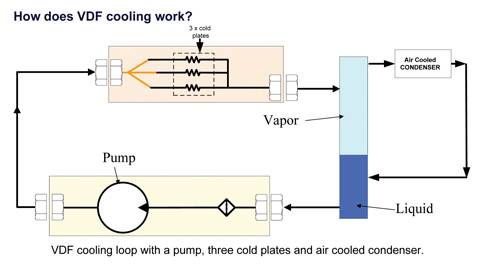
Low-Flow-Rate Pump: Specially adapted from pumps Parker had developed for aerospace and automotive applications, the unique hermitically sealed pump employs the gear-pump method of flow management, where a turning gear within the pump’s body uses displacement to create flow and suction to move the fluid. The pump moves the fluid as a liquid through the loop at a pressure just below the levels where, at ambient temperature, the fluid would flash to gas. As it enters the cooling plate the fluid absorbs the heat from the component, causing some fluid to vaporize. The amount of fluid that vaporizes is directly proportional to the amount of heat to be transferred, which is then taken downstream in a two-phase liquid/gas mixture and away from the component, as illustrated above.
An important characteristic of this system is that the pressure and temperature are allowed to “float” relative to the electrical “work” being performed by the IGBTs. As the workload increases (i.e., amount of switching), the heat load rises causing the amount of vaporization within the cold plates to increase. As the workload diminishes, the vaporization reduces. This is a nearly instantaneous occurrence that does not require sensors and control systems, making it inherently self-optimizing.
Another important characteristic of the VDF system is its isothermal nature, where every cold plate’s temperature is roughly the same regardless of where it is in the system, as the vaporization temperature is constant while the amount of vaporization is variable. This feature eliminates the thermal stacking issues to which water systems are prone.
System Advantages
Parker’s new two-phase liquid cooling system offers a number of distinctive benefits. VDF heat transfer efficiency is significantly greater than water, requiring less fluid, smaller line sets, and lower pump rates. The same dissipation rates provided by a 6 liters/minute water flow can be achieved by 1 liter/minute VDF flow, allowing for a smaller system. Further, the low-flow nature of a VDF system virtually eliminates the possibility of inline cavitations and corresponding potential damages.
A smaller pump also consumes less power, which can be parasitically drawn from the system it is cooling rather than its own power source, which helps free more area. The system is virtually maintenance free. The VDF is non-corrosive, requires no filtering, and is not subject to freezing. The low-power pump utilizes a brushless DC motor rated to provide 50,000 hour L10 continuous-duty life. The hermetically sealed assembly is designed to be leak proof, but should a leak occur the non-conductive fluid will not damage any electronic components. Dry-break connectors make for easily field-replaceable modules needing minimal or no device downtime for scheduled maintenance or failure replacement. The cooling system’s inherent efficiencies and lack of thermal stack-up provide an additional advantage in that the system maintains a fairly tight temperature range. This lack of thermal cycling removes a strain on the turbine’s electronics, thusly extending their useful life.
While these advantages are significant, VDF cooling systems also open more area in which design engineers can do their work. VDF cooling units will not only provide more cooling than water units twice their size, VDFs more-efficient cooling lets the design engineer shrink the power electronics package, allowing for not just a smaller cooling system but a smaller electronics management system.
This new cooling system has been developed by Parker’s Advanced Thermal Solutions Business Unit drawing on core competencies of several of the company’s divisions, including aerospace, electromechanical, flow control, refrigeration, and tubing and fittings. Featuring a number of proprietary and patent-pending elements, the first commercial applications of this new technology began to go online in June of 2009.
Reference:1) DOE/GO-102008-2567, www1.eere.energy.gov/windandhydro/pdfs/41869.pdf


