


For the problem of loosened bolts in the long-term operation of an offshore wind turbine, we proposed a device to detect loosened bolts. The device included a vibration sensor, a signal receiver and transmitter, a CCD sensor, a data analyzer, power supply, a communication line, and a power supply line. The combination of a data analyzer and CCD sensor was used to analyze whether the prefabricated symbols on the bolts change, so as to judge whether the bolts are loose. The whole system (except the vibration sensor) would be in a standby and dormant state at normal times, which is simpler and more reliable under harsh ocean conditions.
1 Introduction
The operating environment of an offshore wind turbine is worse than on land. In the normal operation of an offshore wind turbine, the bolts of the connecting parts are easy to loosen because of the long-term operation and the resultant force of various vibrations.
When the bolts of main working parts are loose, it can cause severe shaking faults. The loosened fixing bolts of the typical generator base can cause the wind turbine to vibrate violently. If the affected parts are not found in time, the steel wire rope cable can be pulled out, and the wind turbine could fall and be damaged [1-2].
According to the existing literature [3-5], the main causes of loosened bolts are:
- A deviation in the installation of the main operating parts of the fan, which leads to a large vibration during the operation of the fan and the gradual loosening of the nuts of the bolts.
- The bolts are not fastened in place, which leads to the gradual loosening of the nuts under the vibration.
- The material characteristics of the bolts are not qualified, and the diameter of the bolts is gradually narrowed under the vibration, which leads to the gradual loosening of the nuts.
At present, the main preventative method to ensure bolts are properly tightened is regular inspection by the operation and maintenance personnel. Because the working environment of the wind turbine is at sea, compared with the onshore wind turbine, the transportation and labor costs are significantly increased. With a proposed bolt loosening detection device for the offshore wind turbine, the combination of a data analyzer and CCD sensor would be used to analyze whether the prefabricated symbols on the bolts change, so as to determine whether the bolts are loose. Compared with other methods of detecting bolt looseness, the strategy of this method is simple. The entire system (with the exception of the vibration sensor) would be in standby mode during normal operation, and the device is simpler and more reliable under harsh ocean conditions.
2 Stress analysis of typical bolts
In connecting the bolt, a connector is clamped by a large tightening pretension in the bold rod, which produces a large friction force to improve the integrity and rigidity of the connector. The typical high-strength bolt used for a wind-turbine tower was designed for shear resistance according to the friction type connection.
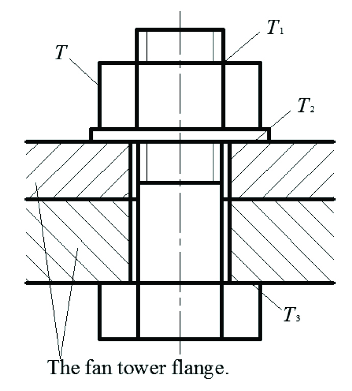
The stress diagram of a typical wind turbine tower flange bolt is shown in Figure 1. Due to the existence of tightening torque T, there is a preload F0 between the bolt and wind-turbine tower flange. The tightening torque T is equal to the sum of the friction resistance moment T1 between the screw pairs and the friction resistance moment T2 between the ring end face of the nut and the support surface of wind turbine tower flange. The friction resistance moment T3 between the annular end face of the bolt head and the support surface of the fan tower flange produces the reverse moment, which is equal to T [6].
![]()
The expression of friction moment between screw pairs is
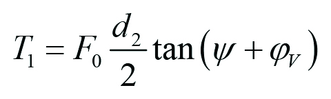
The symbol d2 is the pitch diameter of the thread. The symbol y is the thread-rising angle. The symbol jV is the equivalent friction angle of the screw pair.
Also, the friction moment between the nut and the flange surface of the wind turbine tower is
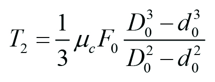
The symbol μc is the friction coefficient between the nut and the support surface. The symbol D0 is the outer diameter of the bolt ring support surface. The symbol d0 is the bolt hole diameter.
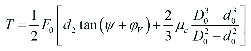
Substituting Equation 3 and Equation 4 into Equation 1, we get:
The methods of vibration measurement in engineering include the mechanical method, optical method, and electrical method. Among them, the most widely used electrical measurement method was to convert the mechanical vibration into electricity and then measure and convert the electricity to make it a signal output.
For a certain type of bolt, the parameter in the bracket of Equation 5 is the fixed value, and the tightening torque T is directly proportional to the pre-tightening force F. Due to this, the pre-tightening force F of the bolt decreases, which further reduces the tightening torque T of the bolt, and finally the bolt loosens.
3 The component of bolt loose judging device
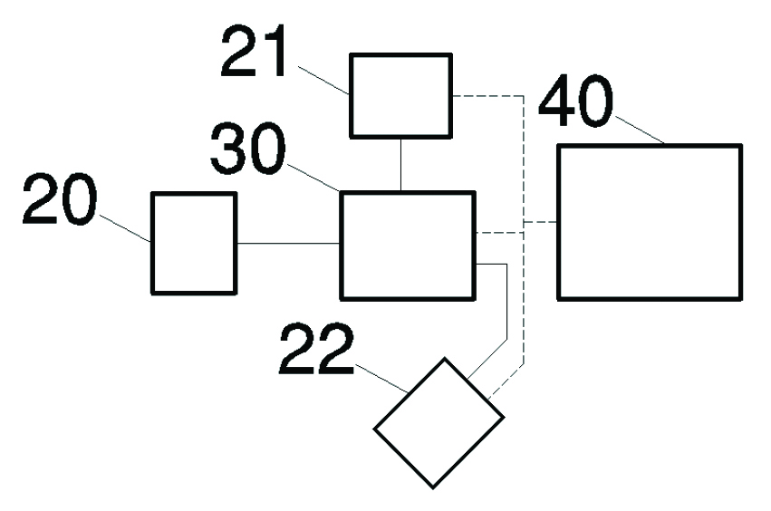
As shown in Figure 2, the loosened bolt judging device for an offshore wind turbine includes a vibration sensor, signal receiver and transmitter, CCD sensor, data analyzer, power supply, the communication line, and the power supply line.
The data analyzer was connected with the vibration sensor, signal receiver and transmitter, and CCD sensor respectively through the communication line. The power supply was connected with the signal receiver and transmitter, data analyzer, and CCD sensor respectively through the power supply line.
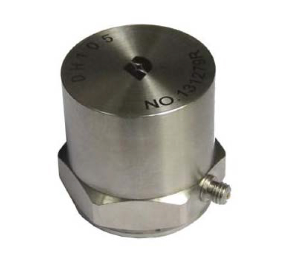
According to their working principles, the specific vibration measuring sensors can be divided into piezoelectric, piezoresistive, capacitive, inductive, and photoelectric types. As shown in Figure 3, the piezoelectric acceleration sensor was the most commonly used vibration measurement sensor because of its wide measuring frequency range, large measuring range, small volume, light weight, small impact on the measured parts, and convenient installation and use. We chose the piezoelectric acceleration sensor here.
4 Operation method of the device
4.1 Preliminary commissioning preparation
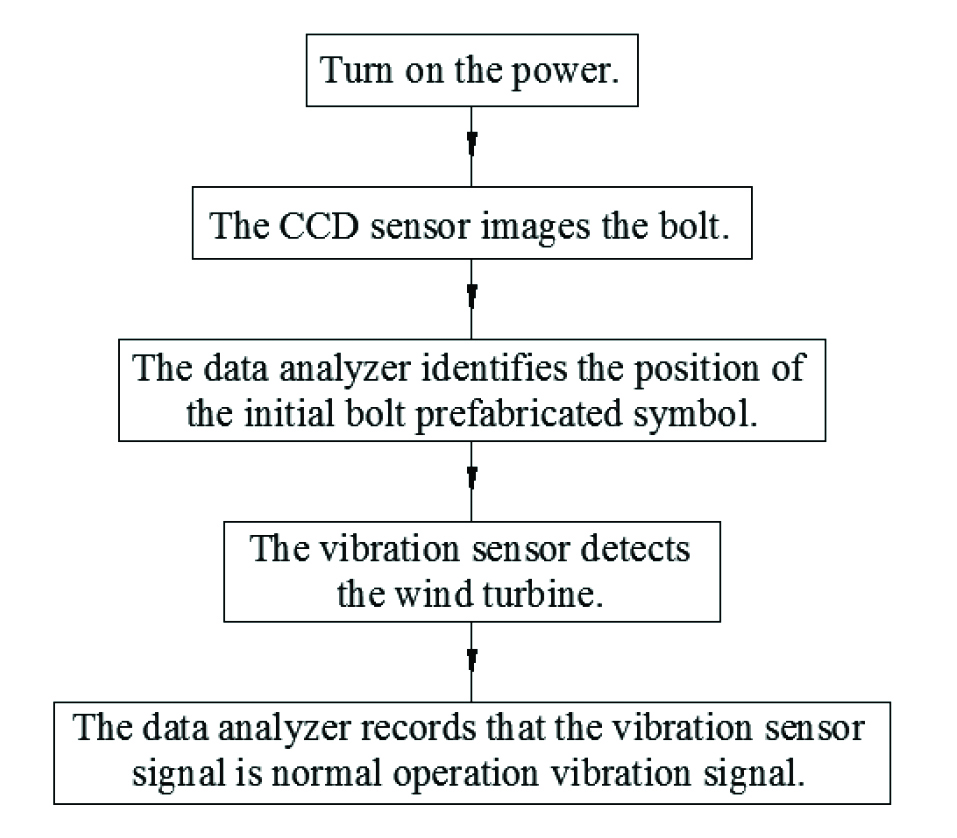
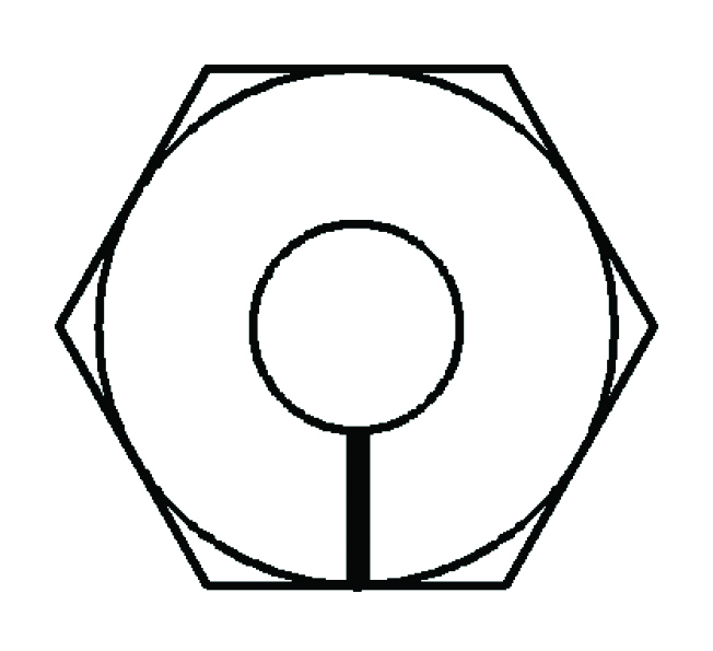
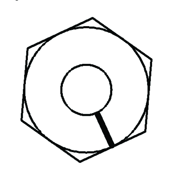
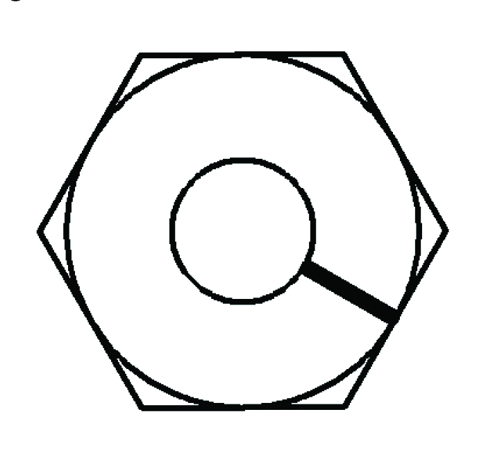
As shown in Figure 4, the power supply was turned on first, followed by the vibration sensor, signal receiver and transmitter, CCD sensor, and data analyzer. The CCD sensor images the bolt, which transmits the initial state image of the bolt to the data analyzer through the communication line. As shown in Figure 5, the data analyzer identified the position of the initial bolt prefabricated symbol in the initial state image of the bolt, and the CCD sensor entered the standby sleep state.
During the normal operation of the wind turbine, the vibration sensor detected the wind turbine in real time and transmits the vibration signal to the data analyzer through the communication line. The data analyzer recorded that the vibration sensor signal is a normal operation vibration signal at this time.
4.2 Daily maintenance and inspection state
At the end of the routine maintenance inspection cycle, the background operator sent the routine maintenance inspection signal to the signal receiver and transmitter. The signal receiver and transmitter will transmit the daily maintenance and inspection signal to the data analyzer through the communication line, and then the data analyzer will activate the CCD sensor to be in the working state through the communication line. The CCD sensor will image the bolt state through the communication line to the data analyzer, and the CCD sensor will enter the standby sleep state.
As shown in Figure 6, the data analyzer identified the bolt prefabricated symbol position A during bolt status imaging, which was different from the initial bolt prefabricated symbol position. The data analyzer connected the signal receiver and transmitter through the communication line, and the signal receiver and transmitter transmitted the signal of the loosened wind-turbine bolt. When the data analyzer recognizes that the position of the bolt prefabrication symbol is the same as that of the initial bolt prefabrication symbol, the signal receiver and transmitter will transmit the normal signal of the wind-turbine bolt.
4.3 Severe shaking state of wind turbine
When the wind turbine shakes violently due to loosened bolts, the vibration sensor will transmit the vibration signal B of the wind turbine to the data analyzer through the communication line. The data analyzer compared the vibration signal B of wind-turbine operation with that of a normal operation and concluded that the vibration signal B of the wind-turbine operation is the vibration signal of an abnormal operation.
The data analyzer activated the CCD sensor to be in the working state through the communication line, and the CCD sensor transmitted the image of the bolt state to the data analyzer through the communication line. The CCD sensor then entered the standby sleep state. As shown in Figure 7, the data analyzer identified the position B of the bolt prefabrication symbol in the image of the bolt status, which was different from the position of the initial bolt prefabrication symbol. The data analyzer connected the signal receiver and transmitter through the communication line, and the signal receiver and transmitter transmitted the signal of a loosened wind-turbine bolt.
Conclusions
The bolt loose judging device for offshore wind turbine included a vibration sensor, signal receiver and transmitter, CCD sensor, data analyzer, power supply, the communication line, and the power supply line. The device included a daily maintenance and inspection state and a severe shaking state of the wind turbine. The combination of the data analyzer and CCD sensor was used to analyze whether the prefabricated symbols on the bolts change, so as to judge whether the bolts are loose. The entire system (except the vibration sensor) has been in standby mode at normal times, which is simpler and more reliable under the harsh conditions at sea.
References
- J.M. Liao, Z. Zhou, C. Zhu, Z.L. Shang, J. Lu, CHN. Mach. Elec. 37, 5 (2019)
- Y. Zhao, B. Han, G. L. Fang, CHN. Thermal Power Generation. 45, 10 (2016)
- B.Y. Hou, Q.H. Qiu, B. Wang, CHN. J. Vib. Shock. 34, 23 (2015)
- Y.G. Li, X.N. Sun, Y.Y. Gao, CHN. J. Vib. Shock. 34, 1 (2015)
- T. Wei, K. Wu, J.W. Huang, CHN. Mach. Elec.8 (2013)


