


Proper quality control and quality assurance procedures are necessary to ensure safe and reliable performance of wind turbines. Various inspection tools and procedures have been developed to assess the safety and reliability of the mechanical components of the turbine, shaft, and blades. However, the concrete foundations are often overlooked. The dynamic and cyclic loads from wind, shaft vibration due to wind, and rotation of blades can expedite cracking in concrete, which might, in turn, affect the mechanical performance of the foundation, its stiffness, dynamic response, and overall structural performance. Cracks and other defects can happen as a result of construction procedure, curing, or simply excessive dynamic loads. It is important to verify these cracks in advance to avoid major structural deficiencies in the future. This article provides a brief review on some of the most common non-destructive tests and structural health monitoring solutions that can be used in the quality control and quality assurance of the wind-turbine foundations. Some of these methods have previously been used for other types of mass concrete elements (such as dams, gas-turbine foundations, etc.), and can be customized for different types of wind-turbine foundations.
Introduction
Over the past decade, Canada has heavily invested in wind energy, increasing its annual capacity from nearly 2,000 MW in 2008, to nearly 13,000 MW in 2019. That is enough to power approximately 3.3 million homes – 6 percent of the country’s electricity demand (Canadian Wind Energy Association, 2019).
There are 299 wind farms operating from coast to coast, including projects in two of the three northern territories. While the quality control, routine inspection, and performance monitoring of the turbine and the blades have significantly developed over the past few decades, the quality control and monitoring of the foundation elements is often overlooked (Charles Nmai, 2010). This is essential in keeping these massive towers grounded and secure. In this article, we will review how non-destructive testing of wind turbine foundations and using real-time structural health monitoring systems can help engineers in the process of quality control, quality assurance, and maintenance.
Wind turbines are often supported on massive concrete foundations:
- The wind-turbine foundation can be as large as 10-15 meters in diameter.
- The foundation block can be as thick as one to two meters, depending on the tower size and soil characteristics.
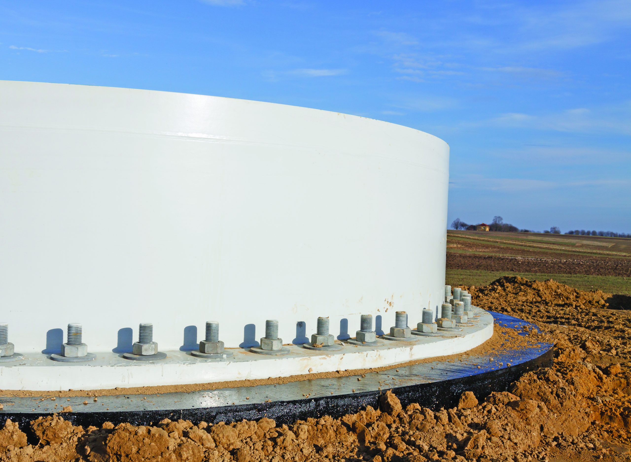
Due to the relatively large dimensions of wind-turbine foundations, these structures are often considered mass concrete. According to ACI 301 (2016), a mass concrete is referred to any volume of structural concrete in which a combination of dimensions of the member being cast and the condition and characteristics of boundaries can lead to undesirable thermal stresses and cracking as a result of elevated concrete temperature due to heat of hydration. Elevated heat in mass concrete components can develop massive temperature gradients in the foundation block. This may result in thermal contraction cracking shortly after the concrete hardens — compromising the structural integrity and durability of the foundation. (See Figure 1).
Wind-turbine foundations have sophisticated congested steel reinforcement to provide stability against dynamic loads. This will make the placement of concrete challenging, and it may result in poor quality patches in the foundation. The congested rebar mesh might contribute to segregation of concrete. Congested rebar complicates the debris/dust removal from the foundation prior to placement of concrete, increasing the chances of poor patches and voids on or around anchors.
While the use of self-consolidating concrete (SCC) and steel fibers can help address some of these challenges by reducing the amount of steel bars, the quality of foundation components needs to be evaluated ahead of installing the tower and the turbine.
The cracking also arises very easily in mass concrete foundations because of thermal cracking as a result of inadequate temperature monitoring, post-tensioning forces (i.e. where anchors are used to connect foundations to the bedrock), and creep. Hence, any interruptions in work or change in work order should be fully recorded.
Another issue that can affect the quality of concrete foundations could be durability issue such as alkali-silica reactions (ASR). Since these foundations are normally exposed to moisture, the risk of ASR will be high wherever reactive aggregates are used in the concrete mix design. This can be addressed during the selection of construction materials.
Quality Control of Wind Turbine Foundations
The quality of concrete is an important task during the construction on a mass foundation. It is often necessary to examine these mass foundations for any signs of premature cracking, voids, or other types of anomalies. Ideally, such testing should be done without damaging the concrete.
A combination of intrusive testing and non-destructive (or minimally destructive) tests are available to assess the quality and integrity of concrete foundations. The range of properties that can be assessed using non-destructive tests and partially destructive tests is quite large and includes such fundamental parameters as density, elastic modulus and strength as well as surface hardness, reinforcement location, reinforcement size, and cover thickness.
Routine quality control tests are necessary to monitor the strength development in mass concrete foundations. The quality control is one of the most important aspects taken into account during the construction and placement of concrete. Proper curing of concrete is also very important.
A range of in-situ and laboratory tests can be performed for enhanced assessment of concrete quality:
- A: Fresh concrete tests such as air content, slump, compressive strength, flow test.
- B: Non-destructive tests for quality control and quality assurance.
- C: Real-time inspection and monitoring (during and post construction).
A. Fresh Concrete Tests
Traditional sampling and on-site concrete testing have been the market standard for the past few decades. The slump test is often used to assess the consistency and workability of concrete. Air content measurement is another effective method in evaluating the properties of fresh concrete. When concrete is placed over dense rebar mesh, a flow test can help engineers assess the workability and flow of concrete. Another major test is sampling concrete specimens and testing them for compressive strength evaluation; rapid chloride permeability test (RCPT) is recommended for durability assessment.
B. Non-Destructive Testing for Quality Control and Quality Assurance
Certain construction issues can result in defects in mass concrete elements. Poor quality concrete with low workability may lead to voids and honeycombs. Moreover, the congested steel reinforcement increases the chances of segregation in concrete. Since most foundation elements are relatively large and considered mass concrete, improper heat control (resulting from cement hydration) can result in significant cracking.
Non-destructive testing (NDT) methods are increasingly applied for inspection and condition assessment of concrete structures and foundations. According to ACI 228 (2013), the increasing trend in use of NDT methods is because of: 1) technical improvement (i.e. software and hardware improvement) in collecting, storing, and analysis of data; 2) economic considerations in assessing larger areas/volumes when compared to intrusive methods; 3) speed of NDT methods in assessing of concrete structure; and 4) ability to repeat the test.
Among different NDT methods, ultrasonic pulse echo (UPE) tomography, impact-echo (IE), and ground-penetrating radar (GPR) are three commonly used NDT methods for subsurface scanning and imaging. This section describes application of these NDT for condition assessment of concrete structures and mass foundations.
Ultrasonic Pulse Echo Tomography
Ultrasonic Pulse Echo (UPE) is a non-destructive testing (NDT) method for scanning sub-surface targets in concrete elements. UPE methods use acoustic stress waves to study the properties of sub-surface layers, and locate defects by identifying any anomaly of acoustical impedance that is different from concrete. Ultrasonic tomography can be used to evaluate the shallow depth deficiencies in the foundations. Depending on the reinforcement pattern, this technique provides a reliable and cost-effective tool to scan concrete for potential defects.
The main concept behind UPE is measuring the transit time of ultrasonic waves in concrete. A modern UPE instrument (called “ultrasonic pulse echo tomography”) consists of an array of piezoelectric transducers capable of exciting the concrete surface through short-burst high amplitude and voltage pulses (see SHRP2, 2013). As the pulse propagates within the concrete, it gets reflected and refracted at the interface of voids or other internal targets. The reflected stress waves are monitored at the receiving transducer. Eventually the tomography concept is used to convert received stress waves to 2D or 3D images. This technique can also be used to image subsurface defects and objects, and show the boundaries of the test area.
Ground-Penetrating Radar
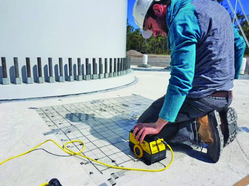
Ground-penetrating radar (GPR) provides a reliable, cost-effective, and non-intrusive tool for scanning and imaging of sub-surface features, such as rebar location, rebar depth, and spacing. (See Figure 2)
A general use GPR device works based on the transmission of electromagnetic waves into concrete and detecting discontinuities of dielectric properties within the concrete area under investigation. When electromagnetic waves arrive at internal objects, such a steel reinforcement, conduits, pipes, or other anomalies such as large air pockets, they partially get reflected in all directions. The reflections moving toward the concrete surface are detected by the receiving antenna. The test is generally performed over single or multiple parallel or perpendicular paths. At any point along the test path, location information and the reflected electromagnetic response are recorded and used for analysis. While GPR can be extremely useful in structure inspection, there are certain limitations to its applications in the field. GPR does not provide any information on the characteristics of concrete materials, or any precise information on rebar size.
Impact-Echo
Impact-echo (IE) is an acoustic, non-destructive test method for the structural integrity testing of concrete structural members such as foundations, walls, slabs, and bridge decks. Develop by Sansalone and Carino (1986), the impact-echo test is based on the generation of stress waves through a short-duration mechanical impact on the surface of concrete element. The test can be used to assess the depth of structural member, and locate potential sub-surface voids, objects (e.g. shield for post-tensioning tendons) and discontinuities.
An impact-echo test device is mainly composed of three main components including an impactor (i.e. small steel balls), a transducer (i.e. piezoelectric accelerometer or geophone), and a data acquisition system. During an impact-echo reading, an impulse (a short duration impact) is applied by a proper impactor at one-single point on the surface of the concrete element. The resulting stress waves propagate into the concrete medium in all directions and reflected between all the existing boundaries and interfaces. When the reflection is arrived to the surface, displacement is induced on the surface of the concrete.
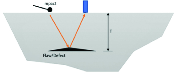
The transducer records the surface movement, converting the measured movement into an analog signal of amplitude vs. time, called “waveform.” The waveform is recorded by a data acquisition system. This waveform is then proceeded for data analysis in either time-domain or frequency-domain. The test method was adapted as a standard test procedure by the American Society of Testing Materials (ASTM C 1383, 2015), “Standard Test Method for Measuring the P-Wave Speed and the Thickness of Concrete Plates Using the Impact-Echo Method.” Figure 3 shows a schematic of an impact-echo test.
C. Real-Time Inspection and Monitoring
Smart monitoring systems can help engineers by collecting accurate and high-quality real-time measurements of foundation element conditions, communicating this information with the control system and signaling warnings should an irregular pattern be observed.
Sensors for structural health monitoring are designed to facilitate the monitoring process and to enable maintenance engineers with decision-making tools, which will ensure the safety and serviceability of these foundations.
Crack Monitoring
Wind-turbine foundations can experience substantial cracking for various reasons: Construction procedures can result in early shrinkage and thermal cracks. Foundations are subject to moisture, which might increase the likelihood of rebar corrosion over the service life. Moreover, the foundation block is subject to vibration and tensile stresses as a result of dynamic wind loading on the tower and turbine. Assessment of these cracks is performed using above-ground methods or through excavation, which tends to be labor intensive and time consuming and might require removing the turbine from the power grid (Perry et al. 2017). Fiber-optic sensors can be used to monitor abrupt changes in stress and strains on concrete and steel bars. Moreover, a relationship between strains in the tower and strains in the foundation can be developed and used as a basis for inspection and monitoring of cracks in foundation blocks.
Tilt Monitoring
Cyclic and dynamic wind loads on the turbine blades and the shaft are transferred to the foundation block resulting in excessive stresses (compressive and tensile) and tilt. Excessive tilt may result in the malfunctioning of the turbines, expensive repairs, and even complete shutdown of wind turbines. Structural health monitoring systems involving tiltmeters can be used to assess the foundation tilting in real-time. The tiltmeters can measure angles of slope (or tilt), elevation, or depression of wind-turbine foundations with respect to gravity’s direction and create early warning of potential structural damage (Bhattacharya. 2019).
Vibration Monitoring
Wind-turbine foundations are subject to different types of dynamic loads, including: wind, wave, and the rotational effects of the rotor (i.e. rotor frequency and the blade passing frequency). The stiffness of operational wind-turbine foundations can change with the loads imparted on the superstructure, which in turn can result in a change in the modal parameters (i.e. natural frequency, mode shape) of the turbine foundation (Adhikari, 2012).
Dynamic response of the foundation block is critical given the fact that these components are subject to rapidly changing wind loads and turbine/blade vibrations. This is critical for the stability and reliable performance of the structure. Vibration-based structural health monitoring solutions use data obtained from an array of accelerometers and measure vertical and/or horizontal accelerations at specific locations. These sensors are deployed for real-time performance evaluation of wind-turbine foundations under variable cyclic and dynamic loads.
Conclusions
Concrete foundations of wind-turbine elements are subject to complex loading conditions during construction, and while the structure is at service. Cracks and defects can happen as a result of construction practice or due to excessive dynamic loads from the wind or vibration of the tower and the turbine blades. Development and progress of cracks in the foundation can affect the stiffness of the foundation, resulting in premature structural deficiencies, and durability related issues.
A combination of non-destructive testing solutions and structural health monitoring systems can be used to enhance the quality control and quality assurance of new wind-turbine foundations. Moreover, these testing solutions can be used to assess the performance of the existing foundation blocks in real-time and trigger necessary warnings to help the asset owners and maintenance managers prioritize their repair and maintenance needs.
References
- ACI 228 Committee (2013) “Report on Nondestructive Test Methods for Evaluation of Concrete in Structures,” American Concrete Institute.
- ACI 301 Committee (2016) “Specifications for Structural Concrete,” American Concrete Institute.
- ASTM C1383-15, Standard Test Method for Measuring the P-Wave Speed and the Thickness of Concrete Plates Using the Impact-Echo Method, ASTM International, West Conshohocken, PA, 2015.
- Canadian Wind Association (2019) “canwea.ca/wind-energy/installed-capacity/” Last visited 15 July 2020.
- Charles Nmai (2010) “Support Systems: What to Consider when Concreting Wind Turbine Foundations” Alternative Power Construction.
- Perry M, McAlorum J, Fusiek G, Niewczas P, McKeeman I, Rubert T. Crack Monitoring of Operational Wind Turbine Foundations. Sensors (Basel). 2017;17(8):1925. Published 2017 Aug 21. doi:10.3390/s17081925.
- Sansalone, M., and Carino, N.J., 1986, “Impact-Echo: A Method for Flaw Detection in Concrete Using Transient Stress Waves,” NBSIR 86-3452, National Bureau of Standards, Sept., 222 p. (Available from NTIS, Springfield, VA, 22161, PB #87-104444/AS).
- S. Bhattacharya, Design of Foundations For Offshore Wind Turbines, Wiley and Sons Ltd., 2019, pp. 202–210.
- Strategic Highway Research Program-SHPR2, 2013 “Nondestructive Testing to Identify Concrete Bridge Deck Deterioration”, Transportation Research Board.
- Adhikari, Sondipon & Bhattacharya, Subhamoy. (2012). Dynamic Analysis of Wind Turbine Towers on Flexible Foundations. Shock and Vibration. 19. 37-56. 10.1155/2012/408493.


