1. Introduction
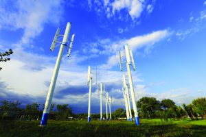
In-service wind turbines operate in harsh environments. While the wind blades are subjected to a high-level of stress, other components of wind turbines are also exposed to difficult conditions. To help ensure the integrity of wind turbines when in-service, it is important to apply efficient and reliable nondestructive testing methods. This paper focuses on the inspection of composite wind blades using ultrasonic phased array.
2. Main Components of a Wind Turbine
A wind turbine is made up of four main components. While the rotating wind-turbine blades generate the aerodynamic torque, the nacelle converts the torque into electrical power. The tower supports the nacelle and rotor blades and provides access to the nacelle. The foundation ensures that the turbine remains upright.
Nondestructive testing helps to ensure the integrity of these components during manufacturing, construction, and maintenance of the wind turbine.
2.1 A Turbine Blade Dissected
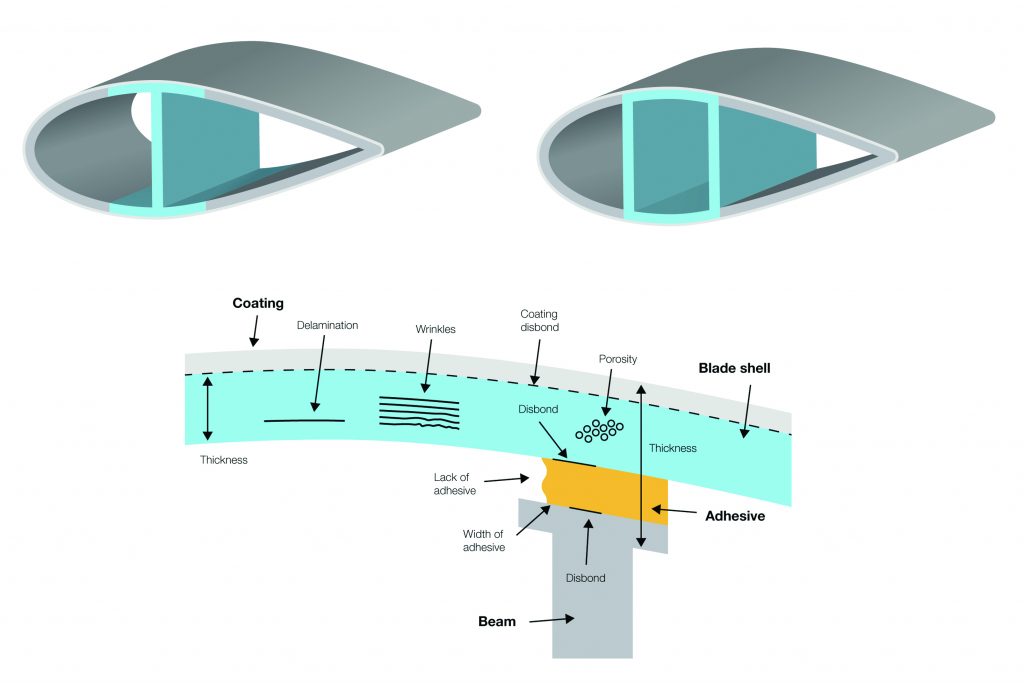
A turbine blade is composed of an outer shell reinforced by one or many internal structural beams called spars. The number of spars depends on the size of the blade. The interior of the blade is hollow. Depending on the manufacturer, the spar could be an I-beam or a box. The I-beam spar is composed of two spar caps and one shear web, while the box spar is composed of two spar caps and two shear webs. In both cases, the spar caps are attached to the skin with adhesive.
A turbine blade is composed of different materials, including glass-reinforced plastic (GRP) fiber, carbon-reinforced plastic (CRP) fiber, balsam/wood, adhesive, resins, honeycomb structures, and coatings. Most of these materials are not qualified as acoustic friendly.
2.2 Types of flaws
Composite turbine blades are prone to flaws that can be the result of the blade’s design or the manufacturing process. These flaws include porosity, disbonds, delamination, inclusions, and wrinkles (out-of-plane waviness). It is important to not only identify and size these flaws but also characterize the width of the adhesive and its position between the beam and shell.
3. Principles of Operation of Phased Array Technology
Phased array technology is based on the capacity to electronically modify ultrasonic beams generated by a phased array probe that contains multiple small elements. When these elements are excited with different time delays (focal laws), the beams can be steered at different angles, focused at different depths, or multiplexed over the length of a long array, creating an electronic movement of the beam.
Multiplexing, sometimes called an electronic or linear scan, is used to perform wind-blade inspection. The sensor consists of a phased array probe that is 25-100 mm (1-4 in.) long and contains between 32 and 128 elements. A small group of elements, defined as the active aperture, is activated to generate an ultrasonic beam propagating normal to the interface. This group of elements is then indexed using electronic multiplexing, creating a true physical movement of the ultrasonic beam under the array with an index as small as 1 millimeter. The electronic indexing is performed so fast that a 100-mm (4-in.) line length is covered by the ultrasonic beams in milliseconds.
3.1 Olympus Equipment for Composite Wind-Blade Inspection
3.1.1 Phased Array Probes
The Olympus sensors used for composite wind-turbine blades are low-frequency phased array probes with the following characteristics: the frequencies available are 0.5 and 1 MHz, and they have 64 elements. The length of the array is 96 mm with a pitch of 1.5 mm, and the elevation is 22 mm. Plastic housing is used to reduce the weight. The sensors are mounted on different probe holders. One is a semi-contact probe holder used for deep penetration, while the other is equipped with a delay line, resulting in an improved near-surface resolution. Both probes holders are available in either a curved or flat configuration. Each probe holder has water irrigation and an encoder attachment.
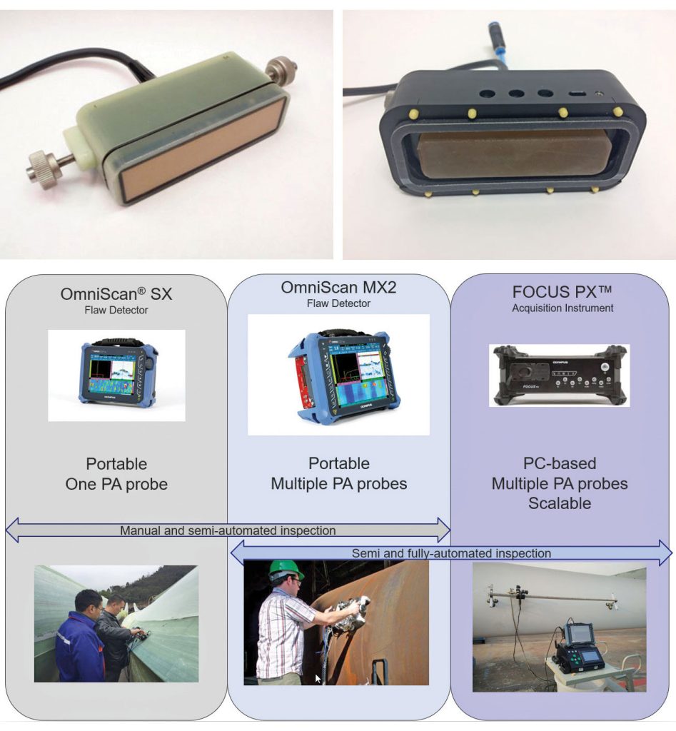
3.1.2 Ultrasonic Phased Array Equipment
Olympus offers a variety of ultrasonic phased array equipment for the inspection of composite wind blades. The portable single PA probe-compatible OmniScan® SX ultrasonic flaw detector and the multiprobe-compatible OmniScan MX2 multitechnology flaw detector can be used for manual and semiautomated inspection. The FOCUS PX™ PC-based phased array and ultrasonic data acquisition unit and the OmniScan MX2 can be used for semi- and fully-automated inspection.
4. Detection Capabilities of Ultrasonic Phased Array
4.1 Spar inspection
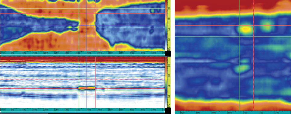
The box spar of a composite wind turbine was inspected with a fully automated scanner mounted on suction cups. The results are observed on a C-scan that represents the mapping of the inspected area. At CRP or GRP flanges, the ultrasound reflects off the inner side of the skin, resulting in a strong echo (represented in red on the C-scan). At bonded zones, if the bond is good, the ultrasound travels through the adhesive and disperses into the web, resulting in missing or weak echoes at the bonded interface (represented in blue or yellow on the C-scan). In Figure 3, the width of the adhesive zones can be measured, and local deficiencies can be located in the bonded area with a sizing resolution of 1.5 mm.
4.2 Bonding Evaluation
A composite wind turbine with deficient bonded zones was inspected with the same inspection configuration as previously described, and the results are shown on the C-scan in Figure 4. Observe that the width of the bonded zone gradually narrows up to an 80 mm long section that is completely disbonded. Localized unbonded areas measuring approximately 20 mm × 20 mm are also present in the good area.
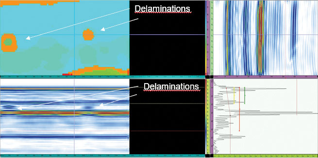
4.3 Delamination
Delamination between glass-reinforced plastic (GRP) and carbon-reinforced plastic (CRP) layers can be easily located using phased array, as these materials are good ultrasound reflectors. Nevertheless, a time-of-flight (TOF) C-scan is a useful tool to discriminate between geometric echoes and delamination as illustrated in Figure 5.
4.4 Adhesive Thickness Measurement
Depending on the adhesive material, echoes from the interface of the shell’s glue and the web’s glue are visible. The distance between these two echoes characterizes the adhesive thickness. Using the appropriate velocity, the adhesive thickness can be evaluated.
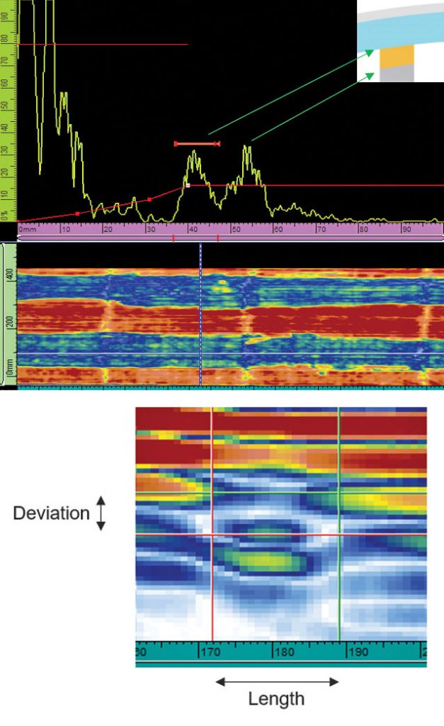
4.5 Detection and Sizing Wrinkles
A wrinkle is an out-of-plane alignment of the composite layer of a wind blade. Wrinkles reduce the blade’s tensile strength and can create out-of-plane delamination. When the right probe frequency is used, it is possible to evaluate the length and deviation of a wrinkle as illustrated below.
5. Ultrasonic Phased Array Inspection Productivity
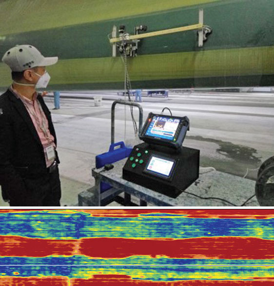
Ultrasonic phased array inspection of a wind blade can be performed in different ways. It can be operated manually with or without an encoder, and it can also be operated in a semi or fully automated manner.
The example configuration presented in Figure 3 is a fully automated system using a two-axis motorized scanner with suction cups holding it to the wind blade. The scanner covers 5 meters in the span direction and 0.5 meters in the chord direction. The OmniScan® MX2 multitechnology flaw detector performs the data acquisition, driving a low-frequency phased array probe. The probe can scan either in the chord or span direction. With this configuration, using an acquisition resolution of 1.5 mm on both axes, the inspection rate is 3 square meters per minute while recording A-scan and C-scan data.
6. Conclusion
Ultrasonic phased array can be used to inspect wind blades with low-frequency probes (0.5 and 1 MHz). The 1.5 mm resolution enables the detection and accurate sizing of small flaws. Defects such as wrinkles, delamination, and disbonds can be detected and sized. Adhesive thickness measurement can also be performed. Ultrasonic phased array technology enables fast inspection while maintaining 100 percent coverage of the part. Off-the-shelf phased array units can be used in a stand-alone configuration or integrated with automated scanners. While C-scan imaging enables analysis at a glance, the use of A B C D images permits a more detailed interpretation. The use of ultrasonic phased array can also be considered for wind-turbine blade maintenance programs.