


Due to the current technological evolution trend, the use of renewable energies seems to be the best suited solution for environmental protection against pollution. This article aims to present the methodology used for the manufacturing and assembling processes of a drag-based, vertical-axis wind turbine, the steps for both processes being addressed broadly. The manufactured vertical-axis wind turbine can successfully function in wind conditions with speeds of up to 16m/s and manages to provide up to 5kW of power. The manufacturing materials used for the execution of the blades include metal sheets, mounted on a structural frame for better stiffness.
The wind-turbine rotor is comprised of three blades installed on a shaft connected to a gearbox, which will transfer the torque to the permanent magnet generator. The whole process is described in the article, and the result consists of the installed turbine ready to function in real-environment operating conditions. The work carried out within this article is relevant to the general know-how regarding wind-turbine manufacturing and installation, as the authors highlight the main impediments they had to overcome when developing, executing, and installing the described model.
1 Introduction
Considering the worldwide energy scenario, it is safe to assume that in the next few years, most countries will face massive attempts to progress from common energy sources to renewables. This statement is reinforced by international major steps in the direction of green energy, supported by programs such as the European Green Deal [1] or by documents as the Paris Agreement [2]. Wind energy represents the second most efficient renewable source of electrical power, according to the data provided in the “Renewables 2019 Global Status Report” [3].
The extraction of kinetic energy from the wind and its transition into mechanical or electrical energy is realized using specifically designed systems for this task. Such systems are commonly called wind turbines and are divided into two large categories according to the direction of the rotating shaft: horizontal-axis wind turbines (HAWTs) and vertical-axis wind turbines (VAWTs). The two are compared in [4], the main highlights being that HAWTs can produce larger amounts of energy compared to VAWTs, but they need a specific work environment (isolated areas with high wind speeds), whereas VAWTs are more efficient in low wind velocities and in turbulent flows, being suited for installation in urban areas and adjacent zones.
In order to improve the efficiency of VAWTs and to help them surpass the performances of HAWTs, new configurations have been developed and tested. Most common configurations include Savonius, Darrieus, and H-Darrieus wind turbines, and new geometries have been developed derived from these, such as the Crossflex wind turbine, combined Savonius-Darrieus rotor, Zephyr turbine or Lenz [5]. This article describes the manufacturing process of the latter configuration, with an emphasis on the used methodology, materials, and equipment.
The Lenz wind-turbine geometry is derived from a combination between the Savonius and Darrieus type and is better suited for functioning in reduced wind speeds. The advantages of a Lenz type VAWT include low-cost fabrication, as its design is not very complicated, and is reliable with an improved starting behavior and good performances in low winds [6]. A mathematical model for calculation activities that present as an outcome the geometric parameters for a Lenz turbine is described in [7]. The design procedure for this type of turbine is discussed, and future work includes the manufacturing of such a model, with applications in urban areas. In [8], a Lenz VAWT with three blades was designed and manufactured using aluminum sheets.
The system was validated through an experimental study. Furthermore, the model was tested with and without deflector vanes used as a method to control air flow direction and optimize the baseline geometry. The study concluded a deflector system can improve the overall performances of the turbine when installed properly, with the angle of instalment having a great influence on the turbine’s efficiency. Some experimental campaigns, such as the one presented in [9], study the blade number influence for the discussed configurations.
The authors design and manufacture a five-bladed Lenz wind turbine, using aluminum sheets and fiberglass. Sivamani et al. experimentally investigate a two-stage Lenz wind turbine with three blades, for a velocity range from 5 to 7 m/s. As a result, they discuss power and moment-coefficient variations [10]. The model investigated was manufactured using a solid mild steel material for the shaft and disks, whereas, for the blades, plywood and aluminum sheets were used.
The most common materials for the manufacturing of the blades for the discussed turbine geometry include thin metallic sheets (often aluminum alloy) and steel for the other components, as can be concluded from the discussed papers. The fabrication methods frequently include cutting processes and rolling.
In this article, for the 3D modeling of the Lenz turbine and final assembly, the SolidWorks software is employed. This CAD tool is largely used for the modeling of various wind-turbine configurations, such as HAWT [11], Savonius [12], H-Darrieus [13], or even combined geometries, such as Darrieus-Savonius, as discussed in [14]. In the following sections, the 3D model for the Lenz type VAWT is presented, as well as the design of the full assembly. Then the methodology for its manufacturing is detailed, including the technological methods used, materials needed, and necessary equipment. In the end, the full assembly is presented.
2 3D Model of the Lenz turbine and the assembly
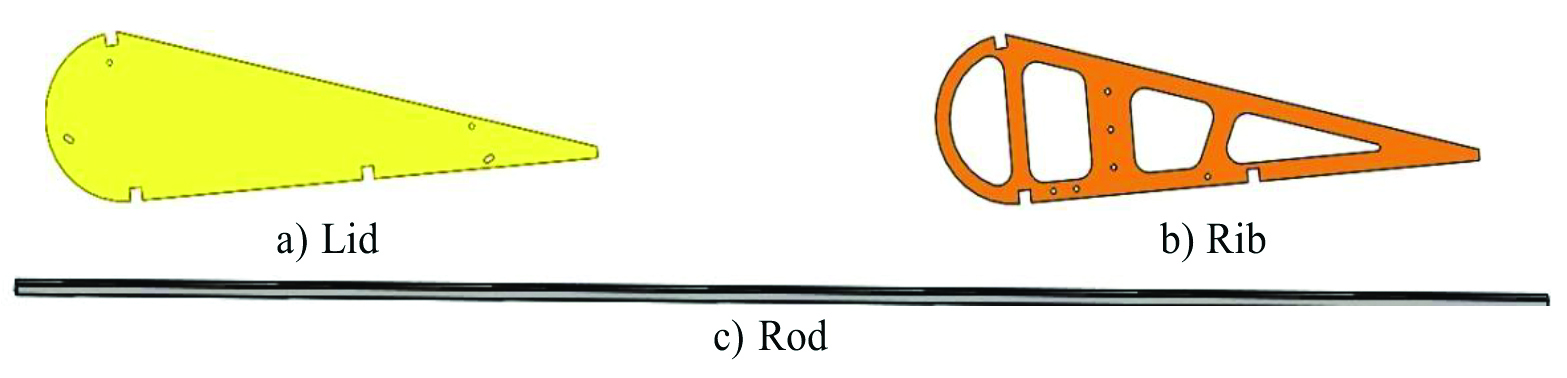
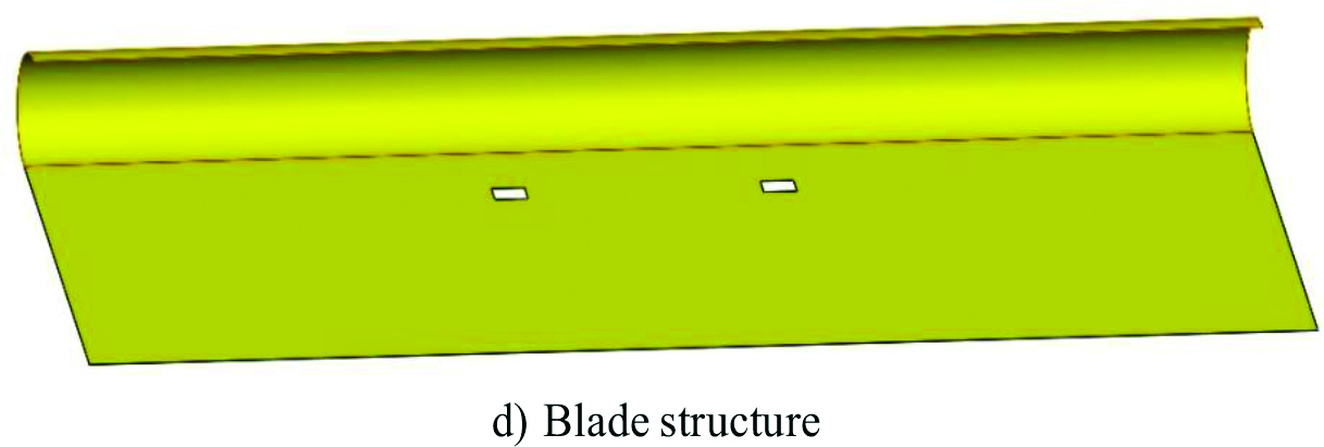
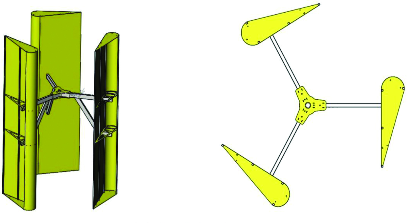
This section will briefly present the Lenz wind turbine integrated in a fully operable assembly, discussing the main parts of the construction. Firstly, the 3D model of the blades was realized using the SolidWorks CAD software after evaluating the geometrical parameters of the turbine according to the mathematical model mentioned in the introduction. The blade consisted of two lids (Figure 1a), one disposed at each end of the blade; two ribs used to connect the turbine’s arms to the blades (Figure 1b); four rods designed to stiffen the blade (Figure 1c) and, finally, the blade structure with a thickness of 0.5mm (Figure 1d). The components are illustrated in Figure 1.

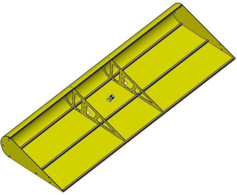
The final assembly for the blade is represented in Figure 2, where the elements mentioned above can be easily identified. The blade’s height was 3 meters, whereas the turbine’s diameter was 2.8 meters.
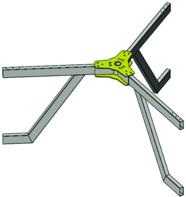
For the purpose of connecting the blades to the shaft, an arm system was designed. The arms were effectuated using a rectangular pipe of 80×40 mm. As the blade is fixated in two different points, using the ribs described previously, the arms were disposed in the manner depicted in Figure 3.
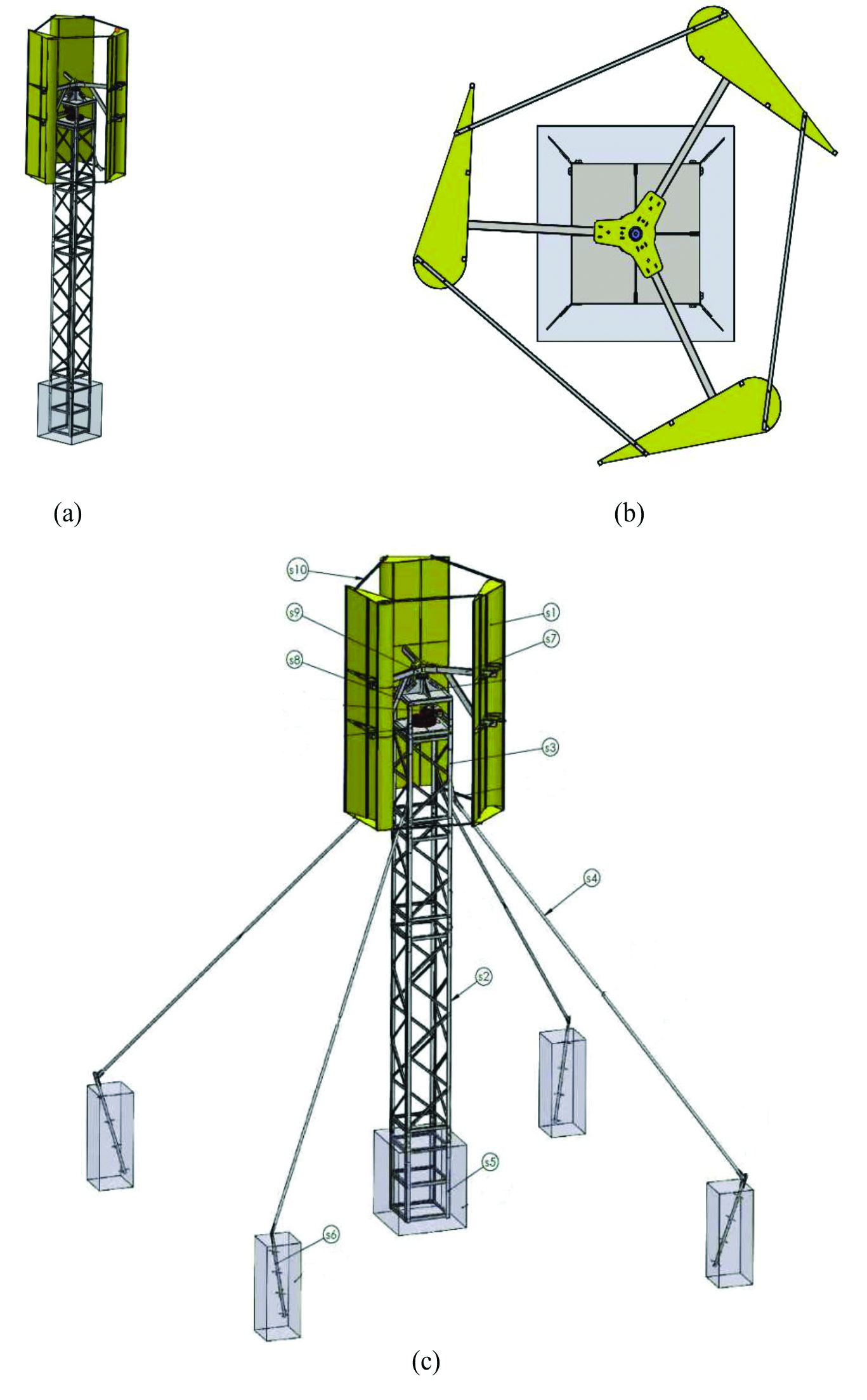
The blades mounted on the on the arm system are illustrated in Figure 4. In Figure 5, the complete assembly for the Lenz wind turbine is illustrated. The full assembly mainly consists of: a support tower (s5), which for better backing is reinforced with four metal tie beams (s6) connected to the main pillar by four metallic poles (s4); the structure of the turbine – the turbine’s upper tower (s3), the generator’s box (s8), the arms of the blades (s7) mounted into a stand (s9) and the blades (s1). In order to ensure the blades’ stability while functioning, they were secured with metallic beams (s10). As it can be observed in Figure 5c, the main pillar has three components: the base supporting tower (s5), the big shaft (s2), and the small one (s3). The integrity of the whole structure is, as mentioned previously, secured using four additional tie beams.
3 Manufacturing process
The main used materials for the manufacturing of the discussed metallic construction include rectangular pipes — S275JR steel, square pipes — S275JR steel, laminated U profiles — S275JR steel, bended U profiles — S275JR steel, and laminated L profiles — steel S275JR.
Some fundamental methods used while manufacturing the wind turbine and the other components of the full assembly incorporate cutting processes, metal machining, and welding.
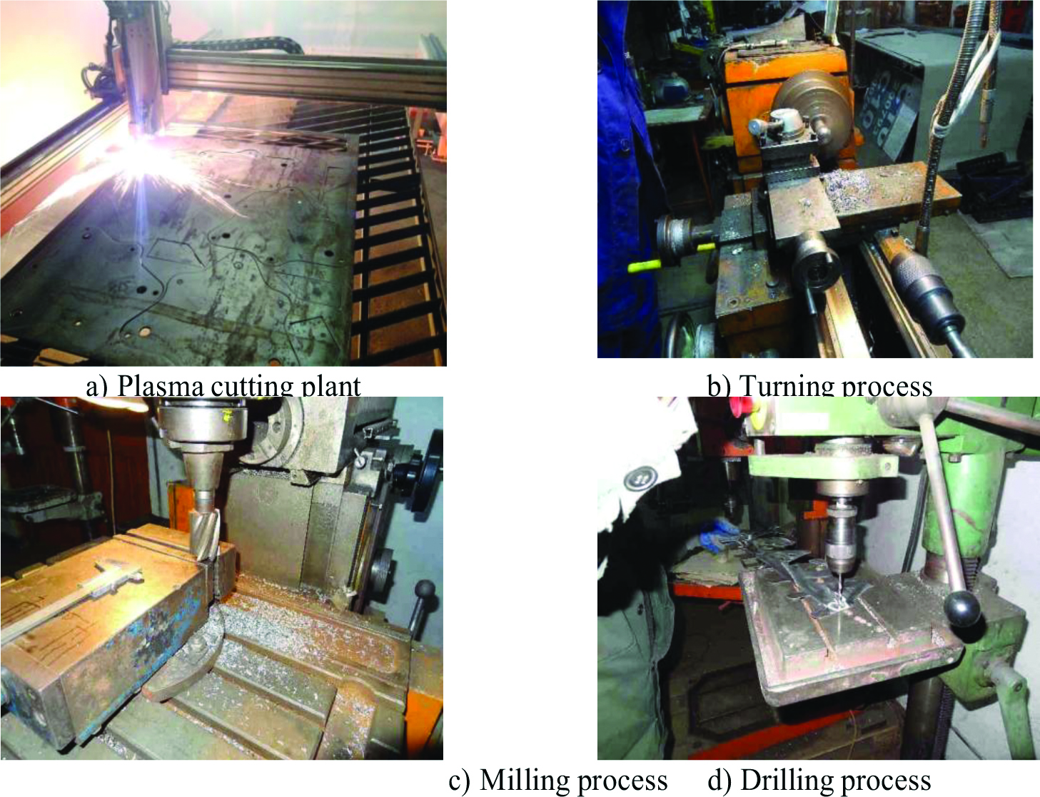
The manufacturing process began with the cutting of the semi-fabricates, using a plasma cut-ting plant, as illustrated in Figure 6a and other metal machining processes such as turning (Figure 6b), milling (Figure 6c), and drilling (Figure 6d).
The specimens obtained as a result of the specified machining processes might present some excess material remains that should be removed. For the deburr process, the selected finishing manufacturing process was vibratory finishing, as it was a rapid and low-cost solution. In order to permanently join necessary parts, electric resistance welding and pressure welding were used as illustrated in Figure 7.
A protective zinc coating was applied to the manufactured parts in an attempt to prevent rusting. Some parts after the galvanization process are shown in Figure 8.
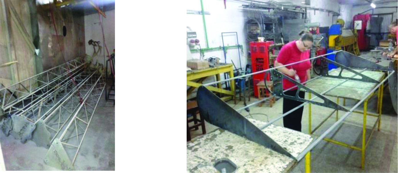
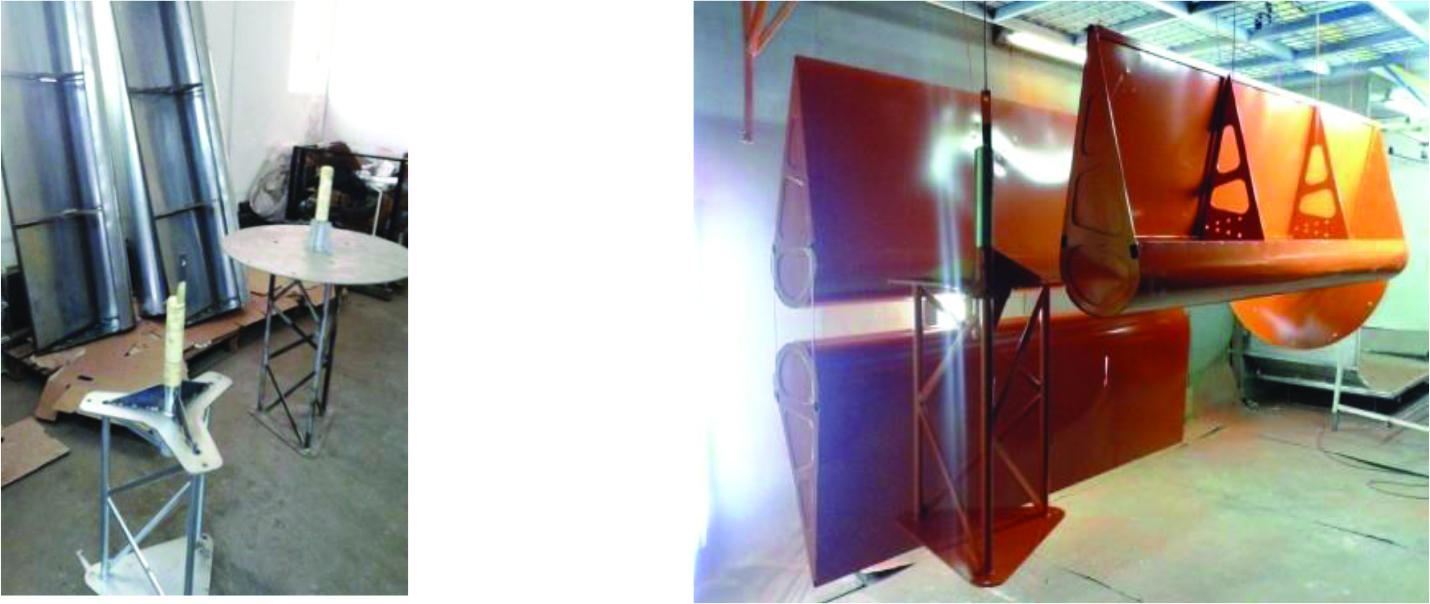
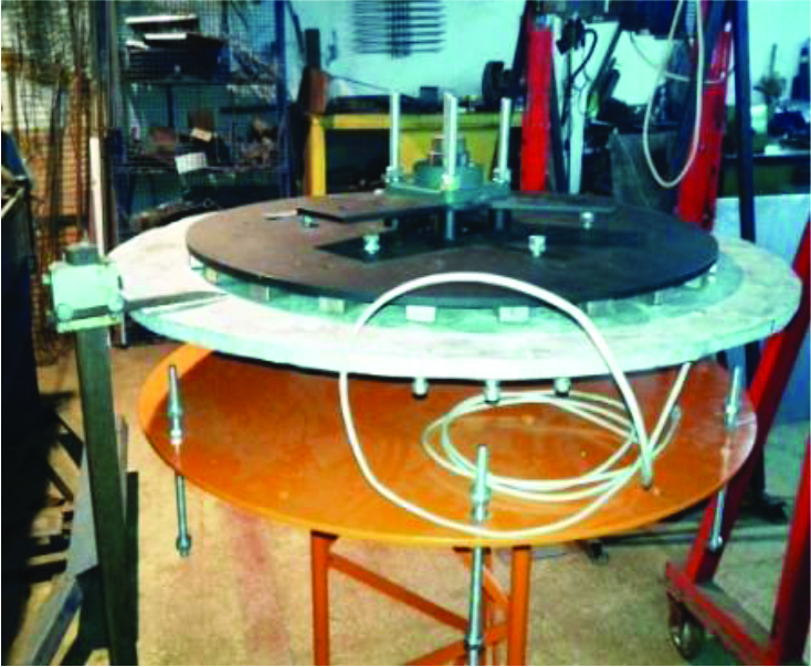
The manufactured blades and parts for the upper part of the main pillar are presented in Figure 9 before and after painting. A generator was designed and manufactured, the result shown in Figure 10. It was placed on the superior part of the designed supporting pillar, as discussed in Section 2 and illustrated in Figure 5.
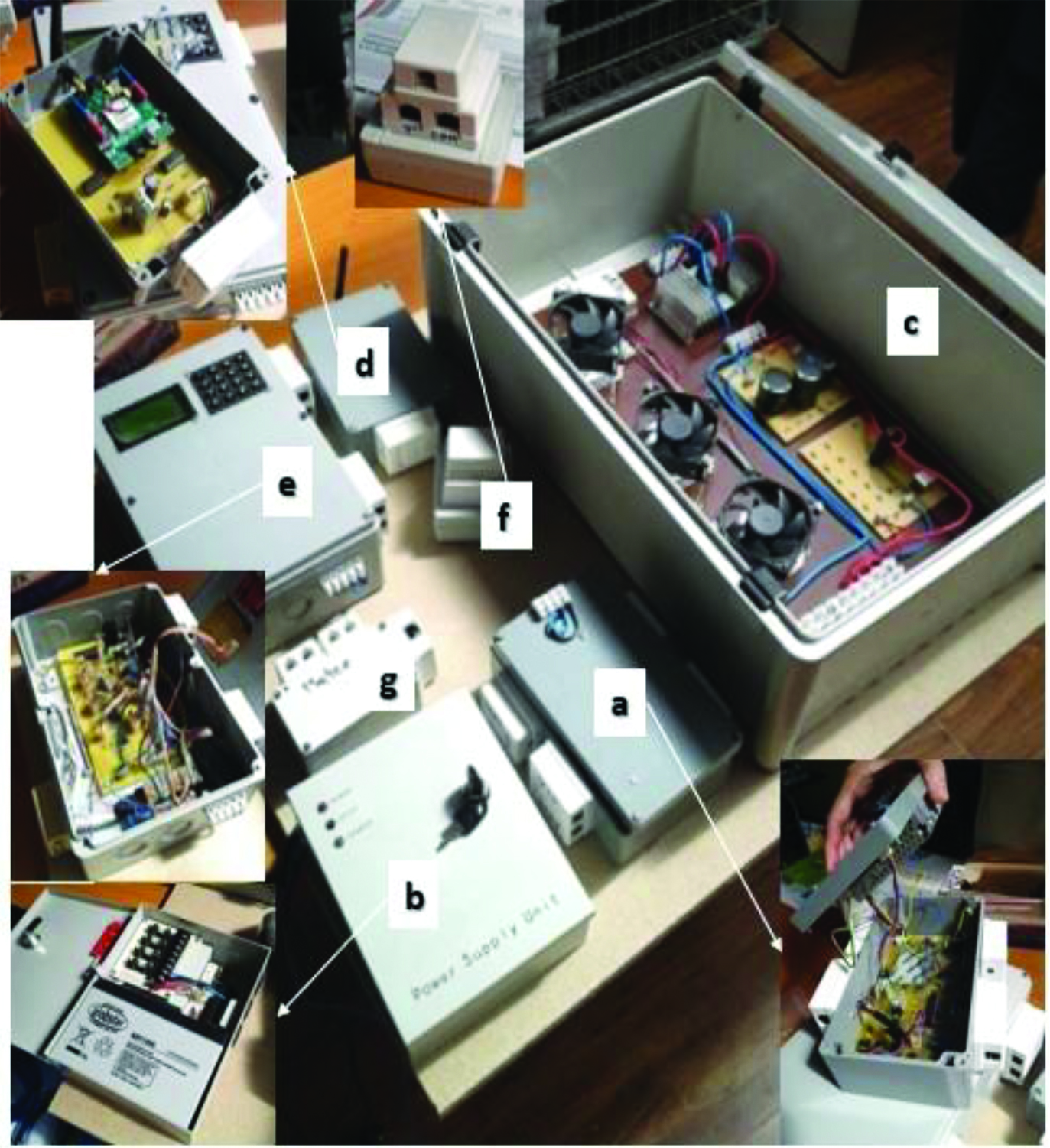
Apart from the main components listed and discussed earlier, a wind-turbine system also contains some fundamental electronical devices. The essential electronics used for the developed Lenz wind turbine include an electronic tool for data control (Figure 11a), a power source (Figure 11b), an electrodynamic brake provided with a voltage switch module from AC to DC (Figure 11c), a GPRS (General Packet Radio Services) module (Figure 11d) that allows the monitorization of the mechanical parameters of the wind turbine (example: tower vibration), a main control data module (Figure 11e), a temperature sensor for the generator (Figure 11f), and a weather module (Figure 11g). All the electronics are illustrated in Figure 11.
The weather module incorporates sensors for the supervision of the following parameters: wind speed, wind direction, precipitations, humidity, and air temperature.
4 Results
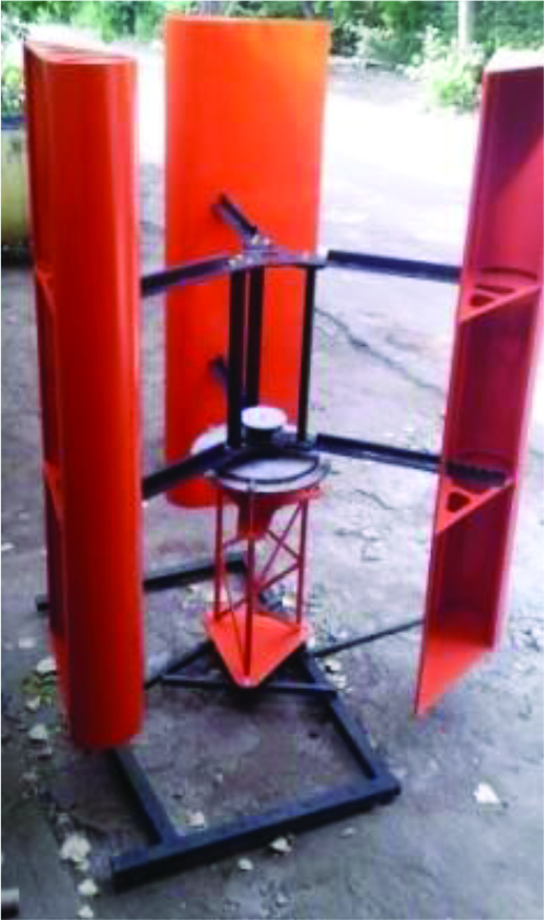
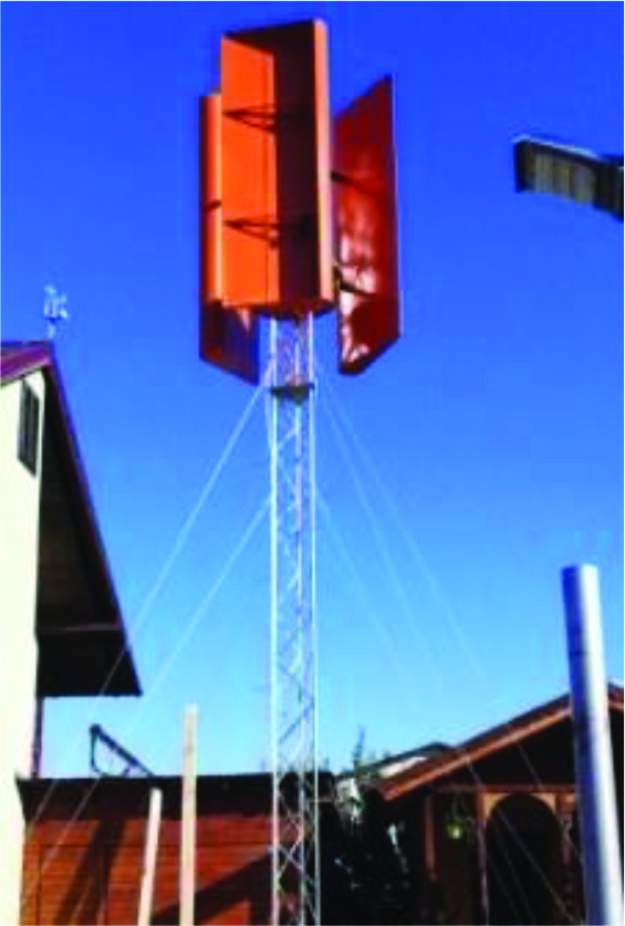
After manufacturing all the parts and applying the necessary mentioned treatments, testing the generator, and revising all the electronics in order to ensure they operate properly, the final assembly was done. The result is presented in Figure 12.
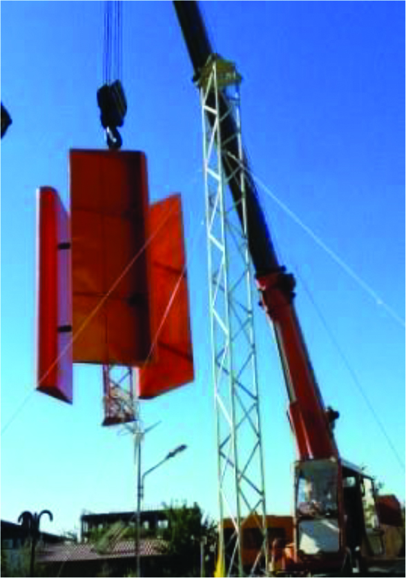
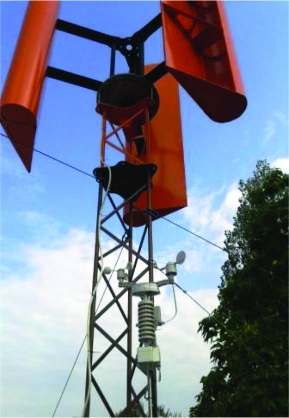
The foundation for the installment of the main supporting tower backed with the four tie beams, was represented by a 25m2 area. For the placement of the Lenz wind turbine on the pillar, a crane is used, as pictured in Figure 13. The final result can be observed in Figures 14 and 15, respectively. The latter figure provides a closer look at the upper part of the wind turbine, and the generator together with the weather station can be noticed.
This article displays in detail the main stages needed for the development, manufacturing, and installing of a Lenz vertical axis wind turbine. Firstly, the 3D modeling of the wind turbine is detailed, followed by the manufacturing methods, and, in the end, the assembly process is described. The used materials and equipment were provided in the manufacturing section. The result consisted in the assembled and installed Lenz wind turbine, capable of generating up to 5kW of power. The metallic structure was provided with a lighting protecting system, and the tower was connected to a certified electrical grounding.
This article contributes to the common expertise regarding the manufacturing and installment of wind turbines, as it concisely depicts the phases included in such a broad process.
Acknowledgments
This work was carried out within POC – Competitiveness Operational Program, supported by the EU and Romanian Minister of Research and Innovation funds, project number POC 9/01.09.2016, MySmis 105890, ID P_40_309.
References
- EU Climate action and the European Green Deal. Available online: https://ec.europa.eu/clima/policies/eu-climate-action_en (accessed on 2/02/2021).
- Paris Agreement 2015, Paris, France. Available online: https://unfccc.int/documents/9097 (accessed on 2/02/2021).
- Renewables 2019 Global Status Report, Paris: REN21 Secretariat, 2019. ISBN 978-3- 9818911-7-1.
- Johari M K, Jalil M A A and Shariff M F M 2018, Comparison of horizontal axis wind turbine (HAWT) and vertical axis wind turbine (VAWT), International Journal of Engineering & Technology 7 74-80.
- Bhutta M M A, Hayat N, Farooq A U, Ali Z, Jamil S R and Hussain Z 2012, Vertical axis wind turbine – A review of various configurations and design techniques, Renewable and Sustainable Energy Reviews 16 1926-1939.
- Nishioka A H and de Almeida O 2018, Study, Design and test of a LENZ-type wind turbine, International Journal of Advanced Engineering Research and Science 5.
- Gohil H P and Patel S T 2014, Design procedure for Lenz type vertical axis wind turbine for urban domestic application, International Journal for Scientific Research & Development 2.
Deori B, Barman S, Das S, Hussain M, Basumatary S M and Sharma K K 2015, Experimental Study on the Performance of Lenz Vertical Axis Wind Turbine, Journal of Material Science and Mechanical Engineering 2 62-64. - Mongkunkeaw T, Kotpai S, Rachsale N, Nakarungsu S, Thungsuk N, Yuji T and Chansri P 2015, A Lenz Wind Turbines Five Blades for Produced Electricity, 2nd Asian Conference on Electrical Installation & Applied Technlology.
- Sivamani S, Premkumar M T, Sohail M, Mohan T and Hariram V 2017, Experimental data on load test and performance parameters of a Lenz type vertical axis wind turbine in open environment condition, Data in Brief 15 1035-1042.
- Hosseini S F and Moetakef-Imani B 2017, Innovative approach to computer-aided design of horizontal axis wind turbine blades, Journal of Computational Design and Engineering 4 98- 105.
- Belmili H, Cheikh R, Smail T, Seddaoui N and Biara R W 2017, Study, design and manufacturing of hybrid vertical axis Savonius wind turbine for urban architecture, Energy Procedia 136 330-335.
- Ferroudji F, Khelifi C and Meguellati F 2016, Modal Analysis of a Small H-Darrieus Wind Turbine Based on 3D CAD, FEA, International Journal of Renewable Energy Research 6.
- Ferroudji F, Khelifi C, Meguellati F and Koussa K 2017, Design and Static Structural Analysis of a 2.5kW Combined Darrieus-Savonius Wind Turbine, International Journal of Engineering Research in Africa 30 94-99.


