


Developers of clean energy are ready to deploy large, efficient 10-MW to 20-MW direct drive wind turbine generators (DDWTG) in far offshore, deep-water wind farms. A new innovative floating foundation system with a unique deployment method will substantially reduce the levelized cost of energy of the DDWTG.
The key is a new large-scale spar buoy (SB) structural design, which is scalable and allows for only one construction formwork design to support and produce all the 10-MW to 20-MW floating foundation requirements. This new SB will be the first to have a double wall hull and use innovative new concrete materials in a design mix that will ensure a minimum 100-year life in any sea state, providing a foundation substructure good for three generations of DDWTG. A telescopic deployment system for the DDWTG, a novel design for a customized deployment vessel, and a round-the-clock 24/7 construction schedule result in a build-out of one complete spar buoy in just 15 days and its deployment in two days.
Construction Materials
Concrete and rebar are extremely well understood materials backed by a thoroughly developed industry. Ordinary Portland Cement (OPC) is the most widely produced man-made material on Earth. However, in the offshore wind industry, the concrete made from OPC (the binder) and coated steel rebar are not durable enough in this corrosive atmosphere. Sulphur compounds in seawater directly react with the large amounts of calcium (approximately 79 percent) in the OPC binder, essentially “rotting” the binder in the concrete, causing rapid failure.
One of the most important new cement components is a geopolymer binder made up of four inexpensive and widely available ingredients: Class-F fly ash, fresh water, water-glass (sodium silicate), and lye (sodium hydroxide). This geopolymer binder can have as little as 2 percent calcium, producing a saltwater-resistant material. In general, geopolymer cement (binders) are stronger; bond well to most materials; have minimal expansion or contraction; are formable; resistant to salts, acids, and alkalis; and are fireproof and waterproof. In keeping with the climate accord of clean energy, the production of geopolymer cement has an 80 percent smaller carbon footprint then a standard OPC.
To replace the steel rebar, a nonmetallic bar made from readily available basalt stone is used for reinforcement. Basalt (generic solidified volcanic rock) is found all over the Earth and is a key component of the mix, enabling the 100-year minimum durability of the foundation structure. The basalt, when heated to a temperature of 1,800 degrees, liquifies and can be poured through a palladium die that produces soft, flexible threads. The threads are laid in parallel and locked together with an epoxy, producing basalt rebar: a waterproof, chemical-resistant, fireproof material with a tensile strength three times stronger than steel rebar. For a smaller diameter in steel rebar, basalt rebar is seven- to nine times lighter for an equal strength replacement. The geopolymer cement in the concrete binds to the basalt rebar on a chemical level in addition to its mechanical bonding. Basalt fiber, much like nylon fiber, is chopped into variable lengths (6-25mm) and used in the mix design for added strength.
Concrete Mix Design
The key to constructability is the concrete mix design. The mix must be efficient to wet-out and bind to the basalt rebar and the chopped basalt fiber for low temperature crack resistance. The geopolymer cement has a high viscosity. To achieve its workability, its placement will need a super plasticizer. A new hybrid super-plasticizer has been designed for geopolymer cement using rice husk and an alkaline that makes it possible to achieve the correct viscosity for placing the mix.
The geopolymer cement (binder) will make up 20 percent of the cement mix. The standard silica sand will be replaced with measured granite sawdust. This will have a beneficial effect on the composite strength, as well as the modulus of elasticity. The specific gravity of the silica sand is 2.83, whereas the granite ranges from 2.65 to 2.85, so the final mix is lighter. The porosity of silica sand is 25 to 30 percent and holds unwanted water in the mix design, whereas the porosity of the granite is almost zero (0.25 percent). The chosen aggregates will be crushed granite (3/16 to 1/4 inch). This mix can be fine-tuned to achieve high strength and density.
Basalt Rebar Reinforcement System
There are no wire ties in the system in keeping with the concept of no-steel in the SB. The only bar ties in the basalt rebar forming will be the pre-tied skeletal lap ties on the long axis of the structure, plus the lateral ties. All ties will be made with plastic clips (injected molded), thus ensuring all ties will have the same value.
The skeletal cages position and centering in the formwork will be achieved with nylon spacer wheels on the outside bars of the cage. The first pour for the first form set, which is 8-feet-9-inches deep off the waste slab and 40-feet long, will require four pre-tied cages, each 8-feet-4-inches high by 10-feet long (plus the lap bar) to reach the full 40-foot length. This skeletal cage requirement will be basically the same for each of the eight formwork pours in the first 40-foot long by 70-foot high concrete placement sequences. This sequencing provides major savings in placement costs. The construction tying of the skeletal cages is a good fall back field assignment.
Spar Buoy Design Element
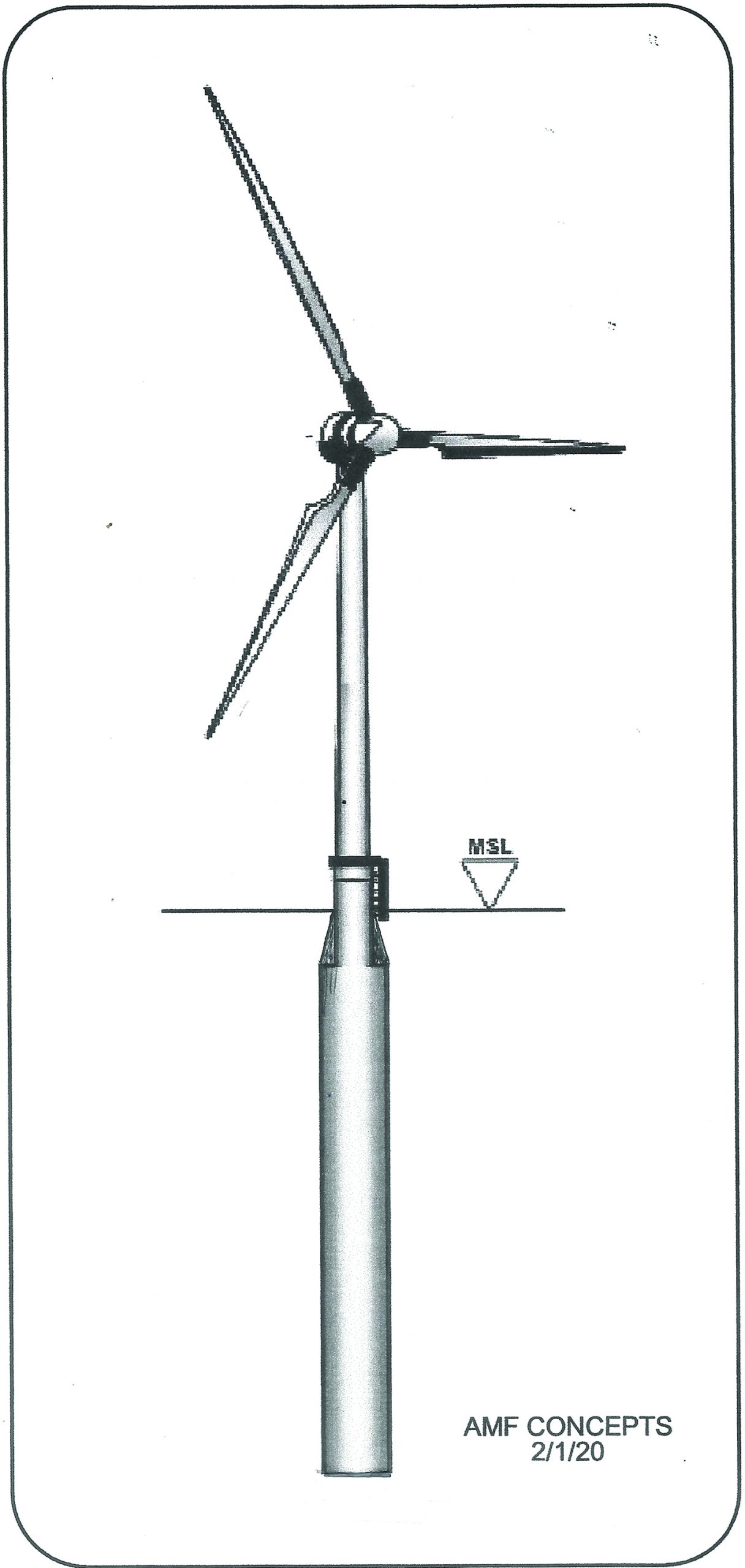
The spar buoy (SB) is 625 feet long overall and is characterized by a small water plane 58-foot outside diameter on its 68-foot-long reduction section on top, and a long, 70-foot cylinder mass far below the surface. This new large-scale SB is designed for countering high weight aloft and a blade sweep equivalent to 5.5 football pitches to meet the many foundation requirements of these new heavy (2,000 ton and up) 10- to 20-MW DDWTGs.
This new SB concept allows for only one construction formwork design to support and produce all the necessary floating foundation requirements for these large DDWTGs. The structural design changes necessary to scale from a 10-MW to a 20-MW DDWTG will not affect the formwork of the SB, only the ballast requirement and the tower bolt up positioning on the interface plunger component used for lifting the WTG in the telescopic SB. This will save two thirds of the constructions custom steel formwork cost.
This new SB will be the first to have a double wall hull to ensure, with proper operation and maintenance, the 100-year minimum design life of the hull. It will also support, as part of this new SB hull, a telescopic system for lowering/assembly of DDWTG tower components, nacelle/hub, into the SB hull. The same telescopic system will then lift a fully assembled DDWTG to the prescribed height above MSL.
Spar Buoy Construction and Deployment
To share insight into the approach of this concept, three of the leading formwork suppliers in the U.S. were asked to submit a bid: PERI — the largest in the world, EFCO — the largest in the U.S., and WADCO — the largest in high complexity formwork in the U.S. WADCO was selected to design and build the formwork. All the formwork produced will be designed for transporting on flatbed trucks or containers. To meet trucking requirements, the formwork components will not exceed eight feet in one axis and nine feet in the other.
Once the components are on site, they will be configured for construction and pour-handling requirements. In this new configuration, they will be ready to be deck loaded on the deployment vessel for transport to the next wind-farm project. The formwork design efficiency is estimated at 15.5 based on both formwork construction sequencing and the development of the construction schedule using three trade crews for the round-the-clock continuous construction of the SB. This efficiency is based on site usage and materials selected to balance the labor requirements for formwork, rebar, and concrete placement.
During construction of the SBs, the balancing of trades and hook time will be achieved by constructing them side-by-side in a dry dock or a land lease fronting a quay side. The site conditions, and the formwork itself, will be well lighted for a 24/7 schedule. One fourth of each construction unit will be covered by a light traveling structure, for all year-round conditions. At float out, the SBs are towed out, via their own hulls, to their position in the farm. Here the station keeping subcontractor, under his contract, will up-end the SB and water ballast the hulls, and then reseal. The SB will then be awaiting a doable sea state and the arrival of the deployment vessel carrying the SBs final fixed ballast and DDWTG. This deployment method saves costly day rates on tugs, ballast vessels, and crew residency time.
The construction sequence and schedule play out in a 24/7, 15-day time frame to produce one spar buoy (SP).
The largest time requirement is in the rebar crew. This sets the construction schedule. In linear structural systems, such as this spar buoy, placing the lap bars through the formwork bulkheads, plus the unforeseen delays in stripping this formwork, can play havoc on the schedule. Therefore, this design will have only one bulkhead, with rubber gromets holes for rebar on the front bulkhead of the void form support by the transfer traveler.
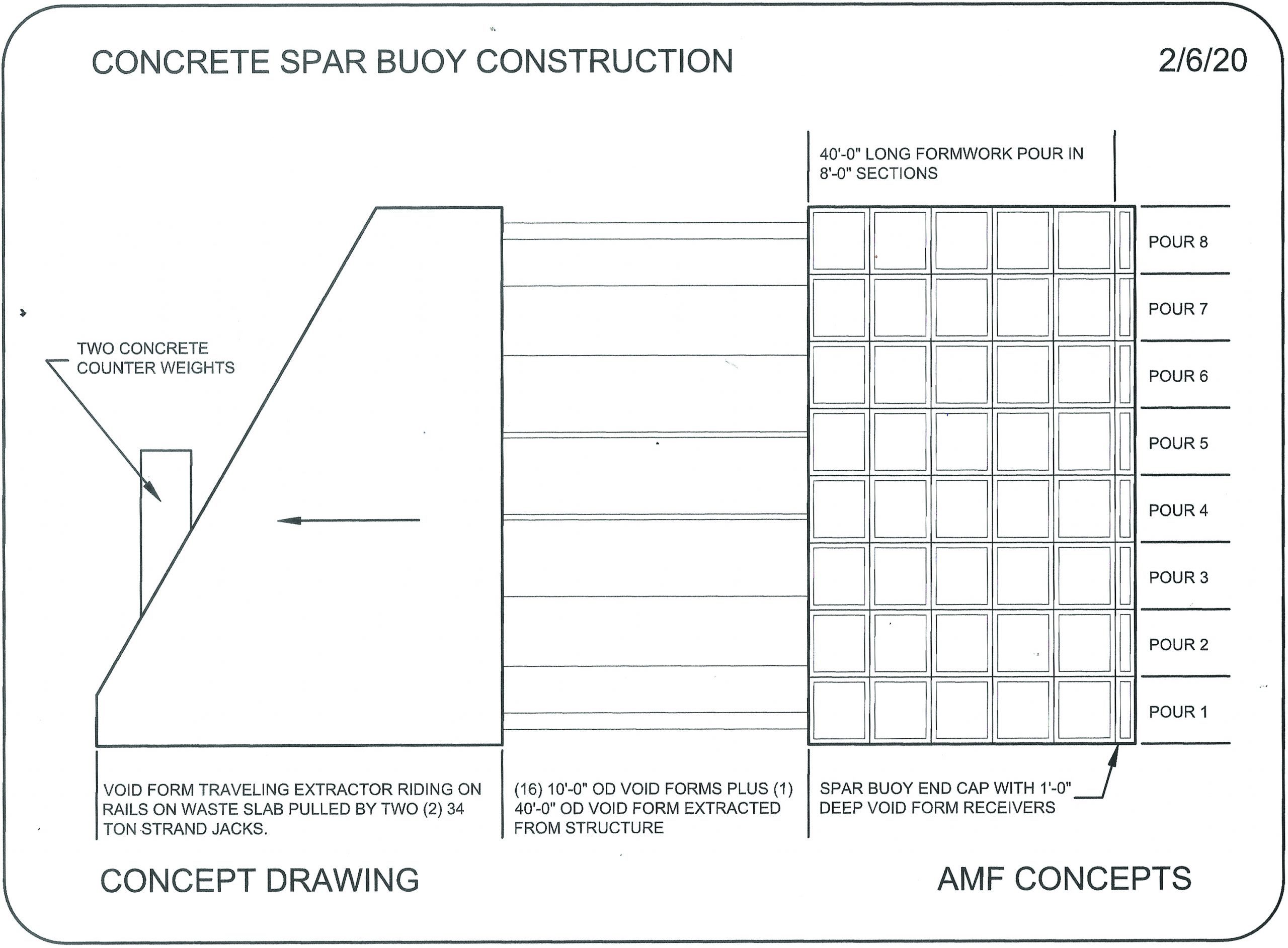
The construction sequence will require building 40 lineal feet of SB at time due to the size of the pours. This will be accomplished with eight individual pours, each 8-feet-9-inches deep by 40-feet long in varying widths. These eight pours will allow the three trade crews to balance the time requirement.
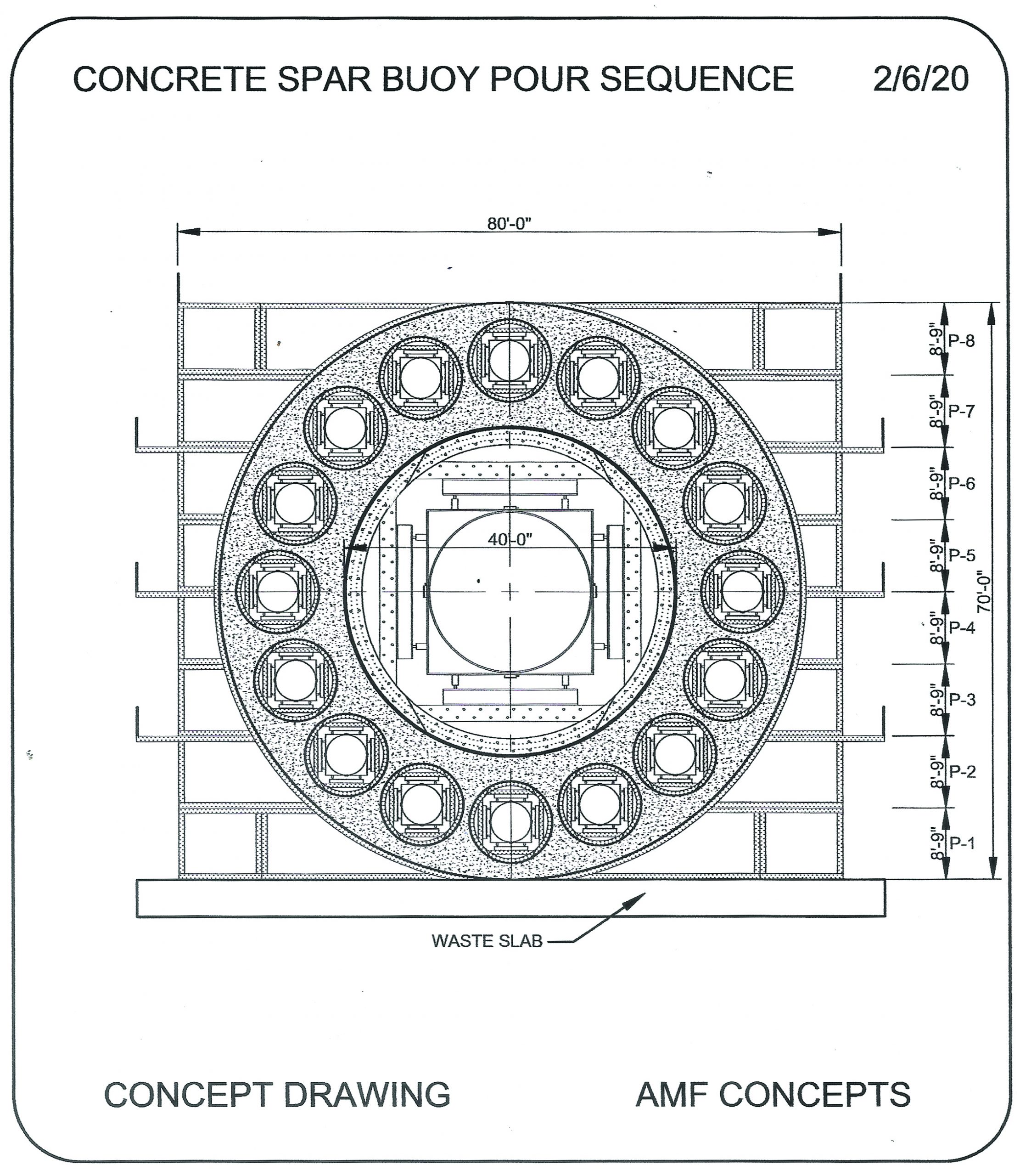
The SB outside formwork, with its eight lifts per side, are designed to work on either side. — top to down and bottom to up. The 16 10-foot diameter void forms, along with the center 40-foot void form, are designed to open and close to formwork place position, and after a pour, to strip position. This is accomplished via 24 double acting jacks built into each void form’s formwork units. All 16 outside and one 40-foot center void form are all stripped in unison by a single computer console on the travelers’ bulkhead bridge.
The formwork carrier pipe, in each of the void forms, is one foot longer on its non-bulkhead end. On the first pour of the project, the SB’s 3-foot thick bottom will support these 1-foot void form extensions with a seal cap over each of their ends, poured one foot into the bottom pour. On all the rest of the pours, this 1-foot extension of the void form carrier pipe is supported by a three-wheel, half-moon cluster of three wheels. These wheels are hydraulically extended to ride on the bottom surface of all the finished cast voids.
The front end of all the void forms is permanently attached to, and supported by, the void form traveler. This structural traveler, the key to the formwork system, will support the front-end bulkhead formwork for the standard 40-foot pour.
At the completion of the pour, all void forms are collapsed and extracted, supported by the traveler on the front end, and by the three-wheel support clusters on the back end, eliminating hundreds of hours of hook time and labor. This traveler concept assures the accurate alignment of the telescopic cylinder formwork within one inch in 625 feet.
The void form traveler rides on the FF-finished waste slab and is guided by a 60-pound rail on either side of the waste slab. Two 55-ton strand jack systems advance the void form traveler in 40-foot increments along the SB bed. The 71-foot height and 56-foot depth of the traveler will support two 50-ton counterweights on its back end over the rails.
The front 10 feet of the traveler supports eight walkways, stacked 8-feet-9-inches high to service the formwork voids. Behind the service walkways are three portable structured rooms, one for the project office, the second a locker room with a walled off kitchen, and the third a lunch/dining area. The traveler, and all its components, are designed to be disassembled for crane handling to new projects.
A Single Vessel Deployment System
The wind industry’s new generation of 10 to 20-MW DDWTGs have caused marine contractors to rethink the deployment of a DDWTG and its floating substructure foundation. At this time, there is no float crane that can lift a small DDWTG’s nacelle of 441 tons and up to 492-feet from mean-sea-level (MSL).
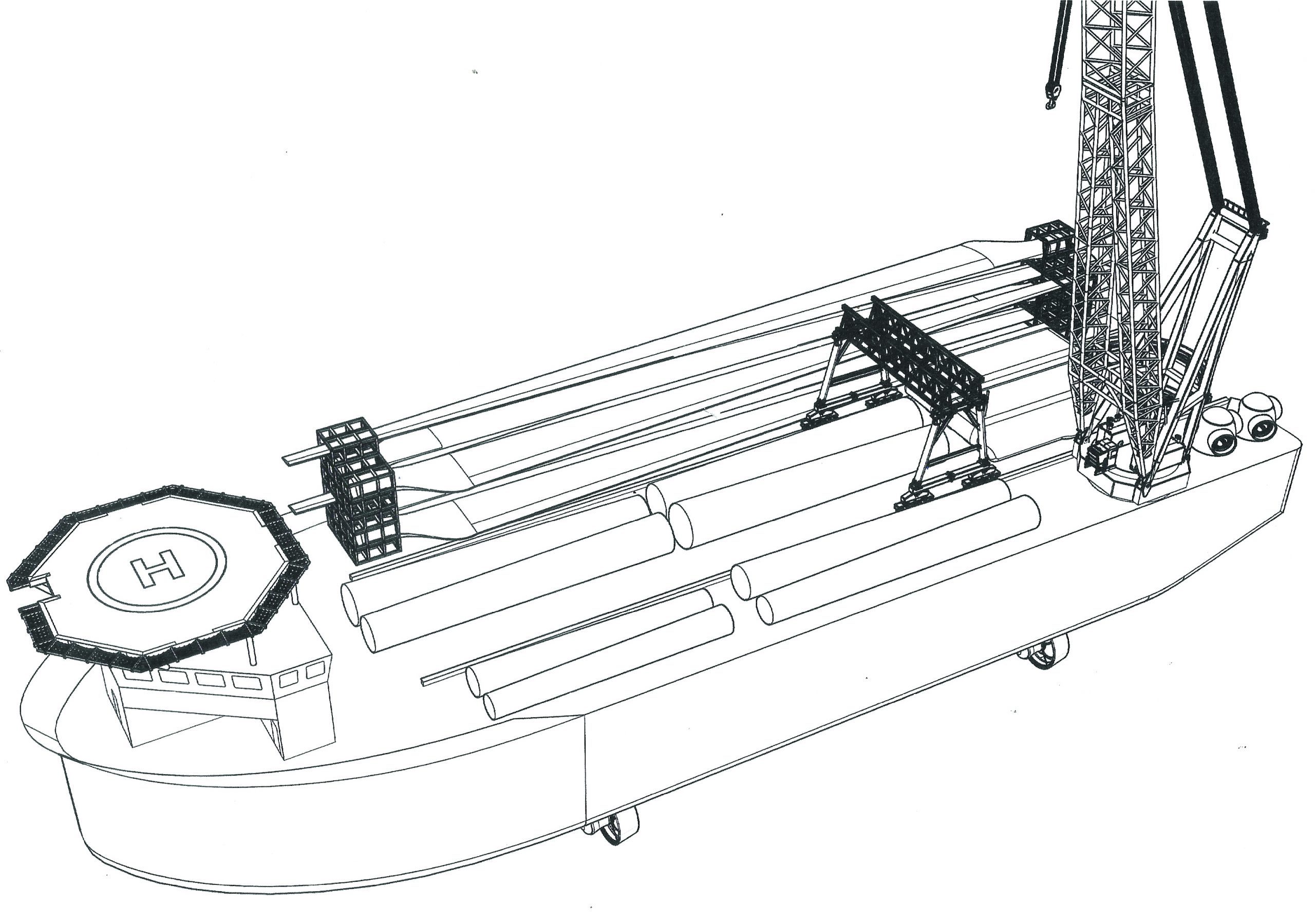
The deployment concept described above has its foundation in the design of an ocean-going deck barge (OGDB). This Jones Act vessel is the key to the transport and deployment of the DDWTGs. This highly sophisticated vessel is designed to transport two DDWTGs in the 10-MW to 20-MW size, as well as their fixed ballast requirements. The OBDB is designed to operate 24/7 to reduce crew residency time. The initial cost opinion studies indicate savings as high as 40 percent for the construction of the SB and its deployment vessel capability.
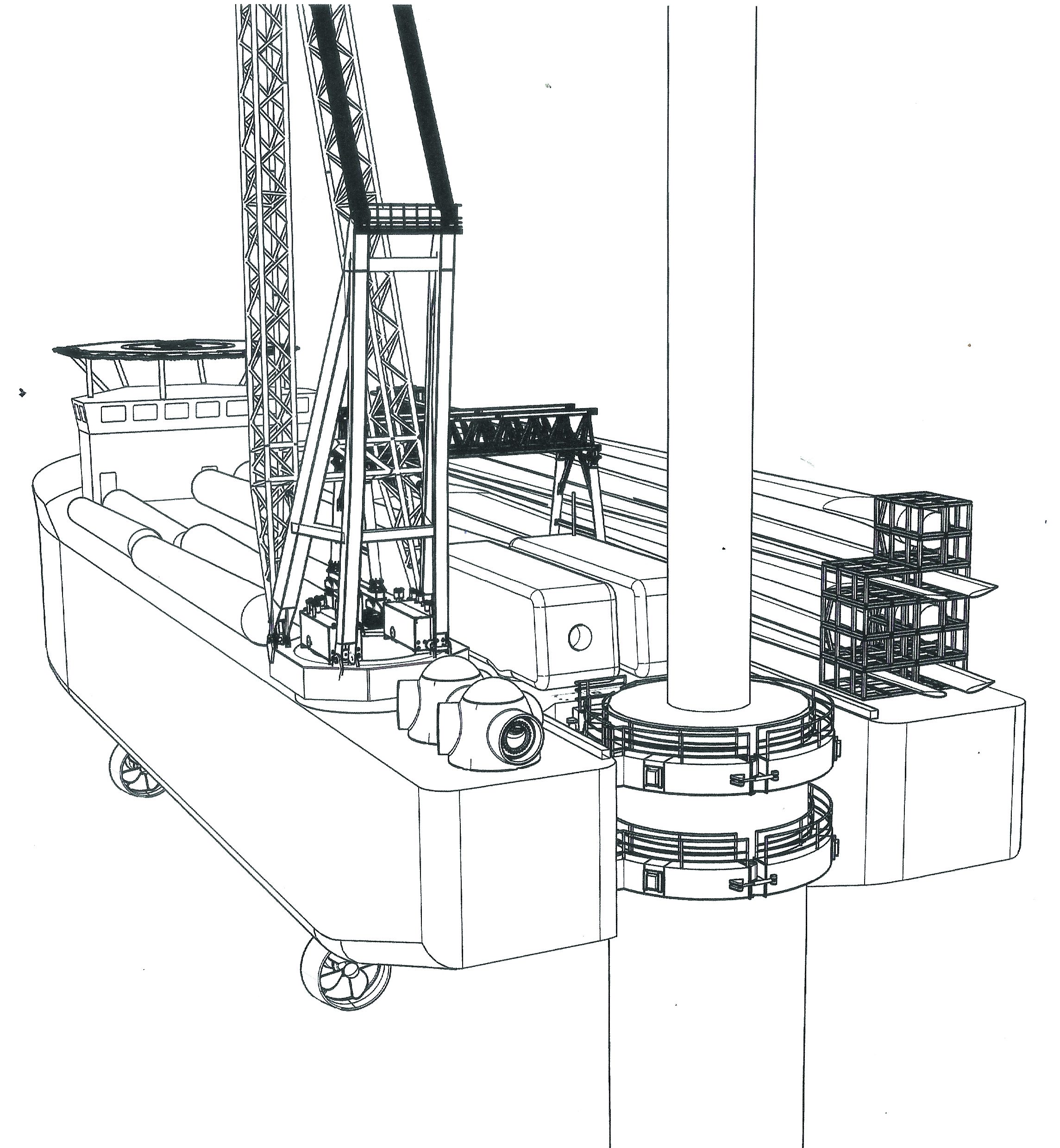
A naval architect has designed a concept OGDB 480-feet in length with a 165-foot beam and a 46-foot deep hull. This vessel will have a 54-foot-wide by 40-foot-deep well notch in the center of its stern. This notch will be used to back down and center the vessel on the anchored SB’s upper reduction section, retaining it for installation of the turbine.
This vessel will meet the new deployment needs of the new heavy DDWTGs. This new vessel will be a self-propelled barge. Four azimuth drive units are used for propulsion and play a role in the vessel’s dynamic positioning system. This OGDB will have a sophisticated structural system to support some of the following deck loads:
- One low-own weight 400-ton pedestal crane, all electric, with a built-in heave compensation system. This crane will be used for lifting all the lighter components into the SB.
- One 800-ton heavy duty gantry crane, with heave compensation, designed to lift the nacelle/hub component over the stern well notch for placement on the turbine mast prior to lifting.
- Two 2,000-ton DDWTG components on the deck.
- Below the deck, two 6,000-ton tanks of pumpable Barium mud ballast for the SBs.
All these loads and their craning movements will require large water ballast systems below deck capable of transferring large amounts of water, at different speeds, in more than one system at a time. The OGDB will have a control bridge forward with a helipad built over a multi-deck crew quarters for both the vessels’ Jones Act crew and the construction crews necessary to achieve 24/7 operations. The OGBD will have two davit sets, each deploying a 24-foot long, closed, self-propelled, 24-man capacity lifeboat.
Spar Buoy Telescopic Foundation Plunger
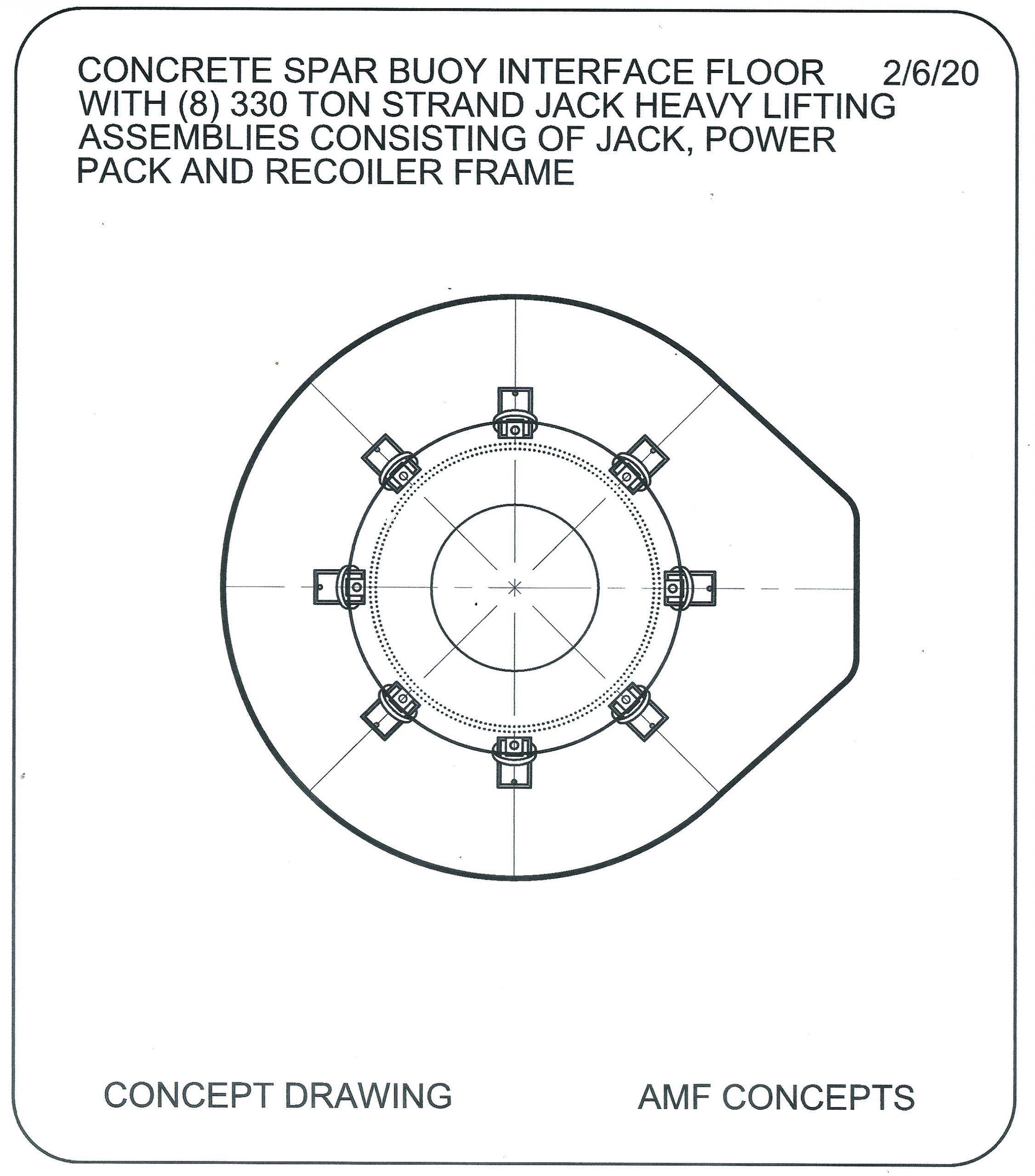
The telescopic cylinder has an inside diameter of 40 feet and allows for placement of a foundation plunger (FP) that can support a range of 10- to 20-MW DDWTGs. The only scale up or down requirements will be in the FP base zone tower bolt-up pattern. This concept allows for only one strand-jack design set to support and lift the new DDWTG size range.
- The FP will be cast in the same basalt rebar and cut fiber concrete mix design.
- The outside diameter of the FP is 39-feet-10-inches.
- The face plate of the FP will have a 20-foot entry hole in its center.
- The face plate will also have eight 10-inch holes, equally spaced and centered 1-foot from the outside FP edge. These holes, for strand jack cable bundles, will run down the full 75-foot length of the FP for tie-off.
- The square base plate of the strand-jack assembly will cantilever toward the center of the FP 1-foot 2-inches from the edge of the FP.
- The FP will have two thicknesses in its 75-foot length.
- The first 50 feet will be 10 feet thick.
- The remaining 25 feet will be 3-feet thick from the outside wall of the plunger and will support eight 1-foot diameter shear pins, each four feet long.
- These shear pins, with a 6-inch void, will be on eight equal spaced centers around the base of the FP skirt and will engage the SB’s main body.
- The FP will be built on site with a separate crew and formwork system. It will be placed and transported on the OGDB/vessel for first lift off into the telescopic lifting system in the SB.
Summation
- System for build-out of one complete spar buoy (SB) in 15-24/7 days.
- New materials for a lighter, stronger substructure, floating foundation.
- Life of the SB substructure will sustain three generations of DDWTGs.
- No need for a plant to produce the SB.
- The SB will be constructed by locals with good skill sets.
- SB design is scalable to support the full range of 10- to 20-MW DDWTGs.
- First to use the SB hull only for transport to the wind farm.
- First to use a twin hull in a SB.
- First to use a telescopic deployment system in a SB.
- First to design a vessel capable of supporting and deploying two DDWTGs.
About the author
Andy Filak is a principal with AMF Concepts. He can be reached at amfconcepts@gmail.com or 310-373-5004.


