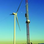
A privately held national infrastructure engineering and construction firm, Henkels & McCoy has been involved in the construction of wind farms for many years. Our expertise includes, but is not limited to, wind farm electrical “balance of plant” work, which includes full wind park electrical integration. The hard work starts from the nacelle and down-tower basic wiring. This includes the lighting systems, installing conductors in the cable tray, and bringing through a vast and complicated conductor gathering system outside the tower area. This is coupled to a low-to-medium wiring harness and tracked to a central point of interconnection. From this point the conductors are laid over to a medium voltage transformer system. The last objective is to install the remaining conductors to the switchgear, at the substation. This will regulate, control, and monitor the wind park during operations.

Many design and engineering changes have occurred since the early days of low-output, low-efficiency equipment during the early eighties. In the wind power technology sector it has been said that the larger the power system is, the more unique issues you’ll find associated with it. Sometimes these issues could start with power electronic designs, pitch and yaw wind controls, bed-plate integration, and the larger picture of the nacelle versus tower design and packaging.
The conventional wisdom on inverter design contains three characteristics. The first could be referred to as software control board programming. The control board programming is a critical path using a variety of algorithms for total power control. The second could be called a gate drive programmed Switching Frequency (SF) on an IGBT (Integrated Gate Bipolar Transistor). SF impacts every aspect of power performance. This will include efficiency, cost, harmonics, ripple rejection, size control stability, audible noise, and utility connection performance. Normally higher frequency is better for all components, parts, and equipment performance. Higher power applications have historically kept switching frequencies to a lower value, less than 10kHz. This is shown in older inverter/converter systems.
There are multiple reasons, and they could range from the base cost of the IGBTs to the cooling plate with the thermal methodology, coupled with the design of the “breadboard,” or installation frame and, last, the total packaging of inverter with all auxiliary essential equipment. The IGBTs and gate drive programming language of controls/firmware is one of the most decisive paths in creating a smooth power conversion system. In the IGBT gate drives, direct hard switching without any soft switching will always lead to a high dynamic/thermal loss during the gate drive “turn on and turn off.” The third and last characteristic will be thermal management for the IGBT’s thermal plate, coupled with the mounted inductor/capacitor requirements for proper backend grid frequency cleanup and power quality.


