


On rotating lubricated machinery oil cleanliness, oil sampling, and oil analysis are generally recognized as the cornerstones for what’s known as “reliability centered maintenance.” For this reason most manufacturers of powertrain components and industrial gearboxes specify oil cleanliness levels in their warranty, but few make provisions for implementing the necessary maintenance procedures. That’s why you need to know about kidney-loop filtration.
For installations that work 24/7, the best choice for extending the service life of a critical gearbox is a kidney-loop filtration unit; the oil dialysis machines for lubricated machinery. Most discussions on this system will focus on the filtration unit, and not on the gearbox it services. A more meaningful discussion will start with the gearbox and lubricating oil, ending with the filtration system that best meets the requirements of the job.
The Gearbox
For most gearboxes mechanical reliability starts with an air breather that vents the inside air space to the outer atmosphere. Without a clean and well-functioning air breather daily temperature fluctuations can generate a pressure rise or a vacuum inside the gearbox. Both are a leading cause of premature seal failure, and too often the original air breather is not up to the job. Figure 1
Generally the vent port is also used for the oil fill port, and it is the only access port on top of the gearbox. In addition to this top port there will be one or more bottom drain plugs, and possibly a side port with a sight glass to check the oil level for the safe and continuous operation of the gearbox.
A kidney-loop filtration system is totally independent of the designed lubrication system for the gearbox. It can be turned on or off, or it can run continuously without compromising the lubrication requirements of the gearbox. When turned on the kidney-loop system must insure that the oil removed from the gearbox for polishing is returned at precisely the same rate. To add the benefits of this filtration system to any gearbox there are three prerequisites: a high-quality air breather to protect the air space above the oil; an oil outlet at the bottom of the gearbox for the suction hose to the filtration unit; and an oil inlet on top of the gearbox for the return hose from the filtration unit.
Oil Viscosity and Lubricating Oils
A youngster may not have heard of Sir Isaac Newton or viscosity, but he understands fluid mechanics when he chooses the big straw over the skinny one every time. Viscosity is a measure of fluid friction, and it is resistance to flow within a controlled space at a given temperature. A kidney-loop procedure will be most effective when the lubricating oil is in full circulation, at normal operating temperature, at its lowest viscosity, and with the gearbox operating at full load. Figure 2
Working back from the gearbox, the first consideration for an efficient kidney-loop filtration system is the connecting hoses and fittings. The next challenge is using the fewest connections, with limited twists and turns and the shortest hoses. But the biggest challenge is getting the filter cart as close to the gearbox as possible while keeping safety for the service technician, the machinery, and the environment front and center.
Filtration and filter media technology have improved immensely since inline oil filters were first introduced decades ago. At the time it was well understood that a machine would run longer on dirty oil than it would on no oil. Filter heads were fitted with a bypass mechanism to maintain an uninterrupted flow of lubricating oil even when the filter element was plugged with contamination. Today the filter heads used on most filter carts are essentially unchanged.
True kidney-loop filtration is independent of the machine’s normal lubrication system. The logic of this type of system says that a filter in bypass is no longer part of the solution, it’s part of the problem since unfiltered oil is being circulated back to the gearbox.
Filter Carts
There will always be a debate over the type and number of filters used on a filter cart. The most common filter carts use two 5-inch diameter spin-on oil filters. The first oil filter is called the prefilter, and the second is called the final filter. Each filter head will have a filter condition indicator and a bypass mechanism, usually rated for 25 psi. When the bypass valve begins to open in the prefilter, unfiltered oil passes through to the final filter. At this point the filter cart is effectively a single-filter unit.
The gearboxes that keep a facility up and running are not in the maintenance shop. They are on a crowded operating floor, on an overhead catwalk, at the end of ship loading boom, or 200 feet straight up in a wind turbine. The filter cart has to be pushed, pulled, or dragged to wherever the gearbox is located. Figure 3
Changing out an oil filter is a messy business and best done in the maintenance shop, not on the operating floor. Back in the maintenance shop the real question is more than the time and cost of changing out just the prefilter or both filters; change only one and there is the risk of cross blending oil grade specifications if the filter cart is used on other applications. And then there is always the cost of the waste and disposal of a gallon or more of lubricating oil.
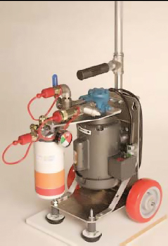
The Kidney-Loop Filtration Unit
For lubricating oils with a wide range grade specifications and viscosities, pump selection becomes an important consideration. The heart of a kidney-loop filtration system is the pump, and the heart of a pump is the rotating group. Figure 4
A fluid can only flow downhill, or move to fill a vacuum. The pump’s rotating group is turned by an electric motor to create a partial vacuum on the suction side of the pump. The vacuum draws lube oil out of the gearbox through the suction hose to the inlet port of the pump, where it fills the cavities of the rotating group. The rotating group carries the oil over to the pressure side of the pump, forcing it through the filter and the return hose back into the gearbox. The performance and efficiency of the pump is determined by the amount of oil that reaches the pump and completely fills each cavity in the rotating group. With the viscosity of the oil specified by the gearbox manufacturer, the four external factors that influence the performance and efficiency of the pump are: the inside diameter of the suction hose; the length of suction hose and number of connections; the type and configuration of the pump’s rotating group; and the speed of the pump’s rotating group.
The most common pump is the gear pump. It works well with hydraulic oil and lighter lubricating oils. By design, it has a limited range for lube oils. The small cavities created by the internal spur gears, the close tolerances required for higher pressure, the knife-edge gear tooth form, and the fixed outer gear housing all combine to severely limit its suitability for the higher-viscosity oils.
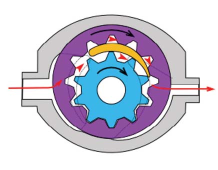
The rotating group of a gerotor pump—sometimes called a crescent pump—is better suited for higher-viscosity lube oils. The motor-driven internal gerotor drives the external rotating gerotor to create larger and fewer cavities with rounded corners. This rolling action of the two gerotors creates cavities that open and close more smoothly. This significantly reduces the shearing of the lube oil in the pump, reducing noise, aeration and cavitation, and delivering a ripple-free oil flow. This puts less stress on the filter media, increasing the dirt-holding capabilities of the filter media. Turning the rotating group at a lower rpm improves all aspects of the pump’s performance, particularly at the higher end of the viscosity curve. Figure 5
The most important feature, however, is having an adjustable relief valve built into the pump housing. This eliminates the need for a bypass valve in the filter head and insures that only polished oil can be returned to the gearbox. When the relief valve is set at 60-80 psi it significantly increases the dirt-holding capacity for an oil filter that would otherwise bypass at 25 psi.
Workplace Productivity
For the service technician, maximizing productivity is essential. One feature of a kidney-loop filtration system that can pay huge dividends is a secondary output flow path. Some gearboxes will have to be drained and the oil transferred to secondary containment, allocated to different applications, or disposed of. By selecting the secondary flow path the used oil can be drained off without fouling the main oil filter. The second outlet can also be fitted with a backup oil filter on the operating floor to continue with kidney-loop filtration without the need to retune the filter cart to the maintenance shop for servicing.


