An attentive car owner knows his vehicle so intimately that he can easily sense when something isn’t quite right. Whether it’s a small noise under the hood, a drip beneath the engine, or a new squeak coming from the front passenger side door, the relationship with the car is a personal one.
The same can be said of a wind turbine technician. Experienced technicians can tell you with a great deal of accuracy which component is making noise and will soon require replacement simply by listening from the ground level. Just like the car owner, this sort of experience is gained through a close relationship with the equipment they visit every day.
In this environment of rapid growth, how does a wind project owner or operator leverage the available experience and extract the greatest potential from their workforce? Rev1 Wind answers this with a solution that has been an integral part of the utility industry for years: digital information capture. Using subcompact computers, handheld devices, and built-in features such as cameras and video recording, service work results that were once recorded only on paper can now be captured electronically and reused by future technicians.
With open-source, Internet-based software, Rev1 has introduced the Tracker DB application to several utility and wind project owners with rapid and enthusiastic acceptance. Using today’s technology and incorporating continuous feedback from service technicians, Rev1 has built a knowledge management system designed to enable fast, accurate decisions by project management thereby maximizing revenue, minimizing downtime, and maintaining continuity of service work on wind assets. Other service companies have methods for recording service work, but the Rev1 Tracker offers something more to owners and operators. Its designers have implemented proven electronic methods to gather, query, and report inspection and service work all for wind project owners and operators to gain a significant competitive advantage. ()
Innovation and the Internet
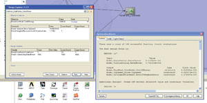
Based on their experience in serving the architect/engineer and regulated utility industry, Rev1 quickly understood the need for the wind industry to evolve to utility standards for digital information capture and management. Originally developed in 2005 for utility American Electric Power to manage such things as turnover packages, drawings, punch lists, , and maintenance tracking, the Rev1 Tracker application has evolved into a much more comprehensive system. Those familiar with typical service documents—either having to complete them as a technician up tower or who may receive it in the project office—know all too well in what condition these can often arrive. “Grease-covered,” “torn,” and “illegible” are all descriptive of a service report, and it stands to reason since the work being accomplished is performed at a height of 50-80 meters and in a cramped working environment. By the time this information is placed in the hands of decision makers, its value has been reduced to markings on a piece of paper, ineligible for cross-reference to other sources of data, rapid fleet-level review, or a quick spare parts search to assure high availability of operating equipment. Handling such information becomes redundant now that several people must extract their relevant information from the same document. The Rev1 solution enables anyone who needs this service information to access it immediately online, to filter and query it according to the type of information required, and to maintain a running database of asset information available for every subsequent technician to review prior to conducting service or inspection work.
21st Century Technologies
Handheld devices such as the personal digital assistant, smart phones, and tablet or notebook PCs are no longer on the cutting edge of innovation. They are now commonplace tools of business and daily life. The use of handheld devices in business yields benefits by converting downtime to productive time and their increased application drives business success by allowing simplification of processes as well as standardization of data. With its newly implemented Tracker application, Rev1 is able to improve the quality and consistency of a service business process by documenting and automating the exact way the process should be completed in every instance. In a mobile software application on a handheld device, Rev1 ensures the appropriate processes are done in the appropriate order. This is accomplished through a variety of means including:
• Requiring specific information to be captured before moving to the next data field or page;
• Requiring a digital photo of the work performed (before and after);
• Automatically capturing time and date stamps for work;
• Automatically checking inventory levels before replacing a part (Inventory Module);
• Routing the technician to a different set of questions, based upon answers (e.g. if equipment is not operating automatically ask question number 4, or if equipment has been repaired, automatically proceed to question number 10);
• If inspection is completed, close inspection file. If steps are incomplete answer question number 120 about hydro station fluid level.
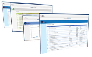
The Rev1 Tracker application can substantially improve the efficiency gain of reporting service work results. One of the most innovative and practical deployments of the Rev1 technology is the near real-time notification of a wind turbine project’s quality inspection. Because Rev1 deploys crews to service wind projects in compressed schedules, they often complete the inspection of an entire project in a matter of weeks as opposed to months. The inspection results are captured, prioritized, uploaded, queried, and reported as soon as the technicians have completed each inspection. Looking for common issues among the results might take an owner several hours of reading each paper report, documenting similar inspection results, and reviewing photos from each turbine. Instead, Tracker’s Internet-based system is immediately available once the inspection results are uploaded. Run a query of priority-one findings and a report is generated showing issues that require immediate attention due to a critical safety concern. Design a custom query to report all findings related to yaw brakes, gearbox borescope results, or tip cable conditions and the information is compiled, accessible, and has immediate enterprise value.
Intelligent Information
Co-designers Andrew Rachel and David Jones, who are long-time veterans of parent company Rev1 Power Services, Inc., have custom-built Tracker to offer full flexibility with a wide range of tools and reporting features. The designers reflected on the mounds of data collected on paper in years past and stored in a file drawer somewhere “for future reference.” Except in rare cases, the data was never reviewed and no “intelligence” or “predictive data” on turbine operation is ever developed. A huge opportunity in equipment betterment has been lost because the technology was not available to create information of value from collected data. Already deployed at multiple utility locations, the Tracker designers developed additional features to allow its use in the wind sector and continue to improve its functionality through feedback from the field. Now used for a variety of wind turbine inspection and service work scopes, the value of digital information available from the Tracker application has increased to a level unparalleled in the paper world.
Tracker is more than a computerized maintenance management system (CMMS) or an enterprise asset management (EAM) tool, although both of these functions are incorporated in the program. This application serves to track the asset from its construction and commissioning phase through the entire life cycle. Information captured during a mechanical completion inspection is available to any technician or business leader who seeks to learn the full history of a component, including problems that may have existed during commissioning. Because of its Web-based versatility, Tracker will provide a real-time view of an entire fleet of equipment, allowing purchasing managers to coordinate local parts inventories, performance managers to better understand fault and serial issues, and business leaders to appreciate the total cost of ownership for a growing turbine fleet. Rev1 has deployed a tool businesses need to drive asset performance and ensure the delivery of projected financial results.
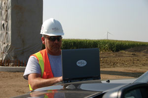
Explaining the functional aspects of Tracker is quite similar to describing how one pays bills online. As an example, a technician who is assigned to conduct an End of Warranty inspection is equipped with a Netbook PC preloaded with the turbine manufacturer’s inspection check sheet. The inspection alone may cover as many as 600 inspection points at various locations on the turbine as well as requiring digital photos, pressure readings, and lubrication levels. Necessary information such as site location, turbine number, date and time is entered upfront. The technician then ascends the tower with the Netbook. At each location the technician will select a checklist sectionto enter task completion notes, data or values from the inspection, and to determine if a digital photo is required. All comments and attached photos become part of the final report. In addition, the technician will select a priority code from one to four indicating a safety concern, immediate attention required, reduced reliability, or operational restrictions. These priority codes are later used to create punch list reports for the customer to address findings from the inspection.
The Rev1 Tracker application is a modular design, meaning only features that are required or requested will be active to the user. The current wind turbine inspection and service database contains thousands of inspection points, yet because a technician might only wish to inspect a Gamesa G52 turbine, for example, only those inspection points will be displayed for his walkthrough. The same holds true from a report review perspective. If a fleet owner had multiple turbine technologies being serviced, they may only wish to query for the Gamesa G52 turbine model, looking for common serial issues that might have arisen from the quality inspections performed by Rev1 technicians.
Moreover, Tracker is designed for the entire lifecycle of an asset, not just construction, commissioning, post-warranty inspection, and service work. Turnover dates, burn-down curve generation/graphs (turnover time v. estimate), project staffing, test equipment calibration dates, model and serial numbers, commissioning test and status, component test forms, and safety checklists can all be integrated into the construction module. Following this construction stage, ongoing maintenance functionality is added to the project application and includes such activities as inventory monitoring, purchasing data, special work orders, tool and material requirements, average time to complete, mean time between replacement, and maintenance and safety procedures. The true value of this information is in the continuity and consistency of the component tracking, from the first time power was applied through all the times a service technician visited the turbine to perform an inspection.
Besides the data storage aspects of Tracker, customers are offered the ability to perform enhanced troubleshooting and monitoring of serial issues in a more technically savvy way. The custom query function allows an owner to drill down into subcategories and even component descriptions and part numbers. Knowing that you’ve prematurely replaced failed hydraulic system o-rings is a good example of a knowledge system that adds predictive value. Failure analysis tools enable the user to filter by model or component number, registered faults, cost of parts, or even by a particular site location.
Fidelity in Design
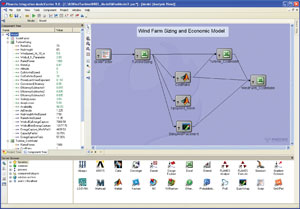
In the MDAO approach, the major subsystems of the wind turbine were considered as black boxes. This type of analysis would typically be performed as part of the site feasibility study. Later, the fidelity of the optimization process could be increased to optimize the wind turbine design at a more detailed level. MDAO makes it possible to move fidelity forward in the design process, enabling site planners and wind turbine designers to make better choices between alternative design concepts at a point in the process when many critical and irreversible design decisions are made. Moving fidelity forward also reduces product development time and expense by enabling the concept design and detailed design phases to largely be conducted simultaneously.
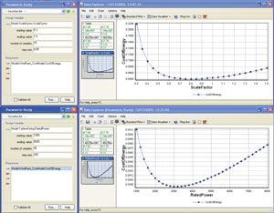
MDAO can advance wind power systems technology by encompassing every aspect of wind farm and turbine design to integrate any or all of the applications used in the design process. MDAO can improve the profitability of wind farms by enabling trade studies that can be used at every stage of the design and engineering process to make better tradeoffs between the many conflicting objectives that are involved in wind farm and wind turbine design.
Ease of Deployment
The Tracker scalability enables a rapid deployment to sites with identical equipment and maintenance requirements, making it even more useful for wind turbine projects. MS Access Runtime environment does not require unique software for offsite use and information can be accessed remotely as long as Internet service is available. If continued maintenance modules are preferred, Tracker is able to upload purchasing data directly to a client system or to integrate purchase order formats into each site’s inventory management module. Additionally, the functionality of Tracker makes it well-suited for failure analysis through a fleet-level interface, adding significant value to efforts in mitigating warranty costs and improving product reliability.
Mobile Service Tracking
Although there are an infinite number of ways a service or inspection process can be automated, Tracker was developed to ensure fieldwork would be completed in a systematic, quality manner. In effect, Rev1 endeavored to build best practices into its mobile application by continuously improving upon the database structure, input devices, wireless capability, and query features provided for the customer. For example, changes to the application design itself can literally be made to each mobile device over the Internet. With a long-term vision, Rev1 is adding features that will enable the application to serve as a training tool for its service technicians. Considering that much of the work completed in the wind field is done remotely, Rev1 sees additional value in having automated processes and instructions such as pop-up messages and training tips built into the mobile application.
As a final example, consider the following scenario: A new wind technician inspects a Vestas V90 wind turbine and identifies damage to the gearbox cooler radiator return hose. He correctly inputs this information into the Tracker application on his Netbook computer. Based on the identified damage to the hose, the inspection application brings up an additional set of questions:
• Location of damage on the hose;
• Type of damage (tear, scrape, puncture, etc.);
• Severity of damage;
• Type of hose (metal sheath, rubber, etc.);
• Serial markings on hose.
For each of these questions a button is available to select for more detailed instructions. This is a powerful inspection-training tool and will help to standardize all answers to ensure the most accurate service inspections possible.
Mobility is an inevitable technology solution for wind project owners. The rise in mobile and wireless technology capability is the catalyst that the wind industry needs in order to keep pace with owners’ eager demands for real-time turbine status, particularly when multi-MW turbines are at risk. Managing project and service data on a utility grade platform such as Tracker will allow wind farm operators to maximize the use of historical information to optimize reliability and equipment longevity, minimize downtime, and improve the analysis of more comprehensive information. Rev1 Wind has created a solid solution that serves to maximize project profitability.


