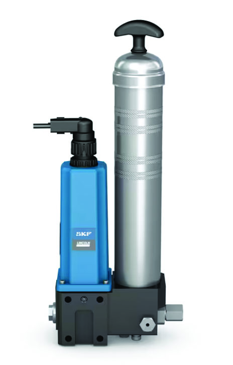
SKF has developed a compact cartridge pump that provides effective lubrication to applications such as small agricultural and construction machinery.
The pump, called AECP, automatically lubricates up to 22 lubrication points making it more time and cost-effective — than manual methods. The pump dispenses grease from standard tubes that are widely available from distribution or retail outlets.
The AECP automatically lubricates up to 22 lubrication points. (Courtesy: SKF)
“Using standard grease tubes makes refilling an auto-lube system as easy as refilling a grease gun,” said Jordan Butler, lubrication product line manager at SKF. “This saves operator time and automates a time-consuming maintenance task.”
Typical applications include dozers, loaders, and farm machinery such as balers and municipal equipment. This type of machinery is typically lubricated manually, which has downsides such as time consumption and the cost of repairs, which is picked up by the equipment rental fleet owner.
The system is also more straightforward for the end-user and keeps both grease and the machine clean. OEMs are likely to see a reduction in warranty claims over traditional manual greasing methods. Other benefits include increased equipment availability and reliability, simpler maintenance, lower cost of maintenance and spare parts, and easier retrofitting.
The AECP requires no special refilling tool or equipment. Grease is stored in standard grease cartridges making it easy to swap out and prime while the motor and pump elements pull grease in a metered way. The use of cartridges also allows for a wide range of lubricants. It also fits into tight spaces and can withstand harsh working conditions and environments.
The pump can be used to create a small progressive lubrication system when combined with SSV progressive metering devices. A built-in sensor gives early warning that a cartridge needs replacing. For more advanced monitoring options, the AECP can be operated with a controller. The pump is ready for sale in North America with global availability in the works.
Emerson has combined its power expertise and renewable energy capabilities into the Ovation Green portfolio to help power generation companies meet the needs of customers navigating the transition to green-energy generation and storage.
By uniting the recently acquired Mita-Teknik software and technology with its own Ovation automation platform, renewable-energy-knowledge-based cybersecurity solutions, and remote management capabilities, Emerson has created a new extension of its power-based control architecture. The resulting portfolio focuses on the emerging clean-energy market to provide simplified renewables automation to help power producers build and scale sustainable operations.
Ovation Green is a reliable portfolio of purpose-built renewables software and automation solutions. Courtesy: Emerson)
“Countries around the globe are focused on transitioning to a clean-energy economy in the coming decades, and while green energy is a simple concept everyone understands, the road to implementation is not always clear,” said Bob Yeager, president of Emerson’s power and water solutions. “With the Ovation Green portfolio, our software, support, and solutions are unified in one system from a single trusted provider to help power producers more quickly, easily, and reliably manage their renewable electricity operations.”
Renewable electricity capacity has seen record growth in recent years. However, transitioning to cleaner energy systems or scaling up existing ones is a complex undertaking for power producers. Wind turbines, solar arrays, lithium-ion batteries, hydrogen electrolyzers, and hydroelectric power all use a wide variety of automation software and technologies. As renewable portfolios grow, the number of applied technologies will multiply, increasing learning curves and adding complexity to operations as solutions from different vendors require additional integration. While some existing systems can provide layers of connectivity between very specific assets, the Ovation Green portfolio will deliver a single set of purpose-built software and solutions that supports different technologies in one standardized, intuitive system.
By gathering, collating, and contextualizing vast amounts of data created by renewable generation and storage assets, Emerson’s Ovation Green portfolio provides a clear view of renewable operations in a seamless space. The portfolio will empower actionable intelligence from a unified platform to drive faster, more informed decisions to increase availability and production while reducing operations and maintenance costs.
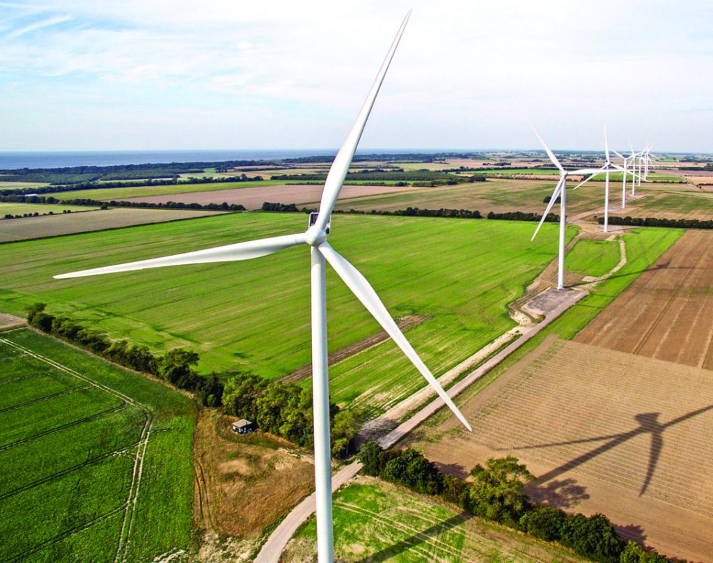
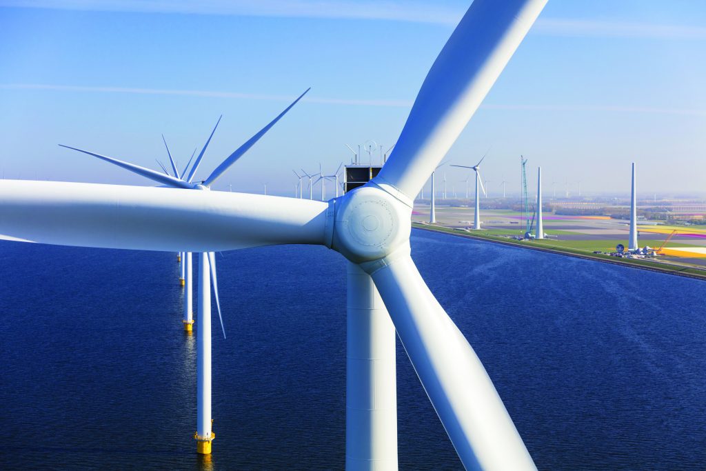
Vestas recently received a 68 MW order from Dirkshof Estonia OÜ to power the Aidu project in Estonia.
Vestas has received a 68 MW order to power a project in Estonia. (Courtesy: Vestas)
The order includes supply, installation, and commissioning of 15 V150-4.5 MW turbines, as well as a 20-year Active Output Management 5000 (AOM 5000) service agreement.
“We are honored to continue the partnership with Dirkhof to deliver this project to Aidu,” said Juan Furones, vice president, sales, for Northern and Central Europe at Vestas. “Aidu will contribute to further decarbonize Estonia, and we are proud to support this project with our industry-leading wind energy solutions.” The site is in Lűganuse parish, Ida-Viru County, in northeast Estonia.The delivery and installation of the wind turbines is expected in the third quarter of 2023 with the commissioning scheduled for the first quarter of 2024.
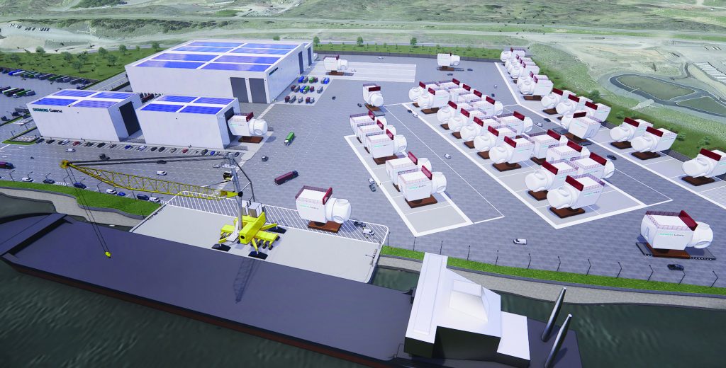
Siemens Gamesa recently announced its intention to build a major offshore nacelle manufacturing facility in New York state, subject to the company’s wind turbines being selected by the New York authorities in their third offshore wind solicitation. The planned facility will be at the Port of Coeymans. It would create up to about 420 direct jobs, support a significant rise in indirect jobs, and represent an investment of about $500 million in the region.
A visualization of the proposed Siemens Gamesa offshore nacelle facility, to be built in New York state. (Courtesy: Siemens Gamesa)
Siemens Gamesa is also committing to localizing several new component supplier facilities, including steel component fabrication, bearings, and composite components, demonstrating the further development of a sustainable local supply chain ecosystem. This could help double the number of jobs created by the facility.
New York expects to procure a minimum of 2 GW of offshore wind energy and up to 4.7 GW in this third round of procurement to achieve a total of 9 GW of offshore wind energy.
The announcement builds on Siemens Gamesa’s track record of establishing major manufacturing facilities in markets with attractive and stable frameworks to meet the growing demand for offshore wind. Siemens Gamesa has secured a site in the state’s capital region; advanced engineering plans and 3D visualizations have already been developed. The facility has been designed with the capacity for potential expansion to guarantee its long-term development.
“The announcement of this proposed facility in New York is a major step forward in our desire to lead the massive U.S. offshore wind market,” said Marc Becker, CEO of Siemens Gamesa’s offshore business. “We’re excited by the opportunity presented by the State of New York to further develop our manufacturing footprint. We have a solid history in delivering on our commitments across the globe, including the establishment of offshore wind-focused plants in Denmark, France, Germany, Taiwan, and the United Kingdom. The numerous economic, employment, and environmental benefits that offshore wind presents are enhanced by solid policies and frameworks, which are critical for financial success.” The proposed facility and supplier network in New York would supply components for all Siemens Gamesa offshore wind power projects along the U.S. East Coast.
The wind-power industry’s challenging period continued in 2022 due to unexpected geo-political uncertainty, an accelerating energy crisis, and high inflation. In this environment, Vestas’ fourth quarter results were negatively affected by additional challenges. The negative impact in the fourth quarter causes the full-year results to be lower than the outlook, primarily driven by a confined number of project delays, an impairment on the V174-9.5 MW turbine and increased warranty provisions.
In 2022, Vestas made strategic and commercial progress in terms of strengthening operations and substantially raising prices that indicates Vestas will deliver improved financial results in 2023. Activity levels in 2023 are expected to be lower than in 2022 followed by a step up in 2024 where installations in key markets are projected to increase.
Vestas’ preliminary and unaudited 2022 results show a total revenue of EUR 14.9 billion Euros. The Service business accounted for 3.155 billion Euros of the total revenue, corresponding to a year-on-year growth of 27 percent. The higher-than-expected revenue growth in service thereby partially offsets the lower-than-expected power solutions revenue, which has been affected by delays in execution.
Based on preliminary numbers, the EBIT margin before special items was 8.0, primarily driven by isolated events in the fourth quarter of 2022 as well as delays in a confined number of projects by the end of the fourth quarter. In the fourth quarter, additional warranty provisions of 210 million Euros were made. The higher warranties primarily relate to increased repair and upgrade costs and a few select cases. As a result of an expected challenged profitability and lower order intake for offshore projects using the V174 turbine, an impairment of 95 million Euros has been made on that platform in the quarter.
Increasing the price on wind turbines is and has been a necessity to address the external cost inflation and ensure the industry’s long-term value creation. Order intake in the fourth quarter was 4.2 GW with an average selling price of 1.15 million Euros per MW, a sequential increase of 8 percent. For the full year of 2022, this resulted in an average selling price of 1.07 million Euros per MW (onshore only: 1.04 million Euros per MW).
Free cash flow amounted to 1.283 billion Euros in the fourth quarter but was negative 953 million Euros for the full year compared to 183 million Euros in 2021. This development was primarily a reflection of the lower profitability and resulted in a net debt position of 46 million Euros.
In 2023, high inflation levels are expected throughout the supply chain and reduced wind-power installations to affect revenue and profitability negatively. The lower level of installations is caused by slow permitting processes in Europe as well as dampened activity levels in the U.S. due to a steep ramp-up ahead of a busy 2024 driven by the Inflation Reduction Act. Increasing prices on order intake is an offsetting factor, but still leaves Vestas challenged on profitability in 2023.
Global height safety specialist Guardian recently announced its upgraded line of Self-Retracting Lifelines (SRLs) at the World of Concrete show in January. Improvements to the line include more robust shock packs to withstand greater fall forces, thicker cables, and redesigned braking systems — all of which combine to provide greater dynamic strength. The enhanced range also features an updated design that brings the SRLs together under a unified look.
Guardian is rolling out the upgraded line of Self-Retracting Lifelines over the next few months. (Courtesy: Guardian)
“Testament to our belief that safe should be simple is the dynamic new look that spans our entire SRL family,” said Judd Perner, product and engineering director. “We look forward to rolling out our new Guardian industrial design across our broader height safety range over the coming months.”
“As the industry leaders in SRLs, we think it’s our job to lead the way — continually challenging ourselves to set new benchmarks in robust safety, durability and useability,” said Scott Lapier, product manager. “We have treated this year’s introduction of a new ANSI standard as an opportunity to advance our entire SRL family. Our growing new product development team has explored every aspect of the user experience — from design and performance, to ergonomics and use to deliver a range that is even safer, stronger, and simpler to use.”
Guardian is showcasing the new range in advance of the August 2023 effective date for the ANSI Z359.14-2021 SRL standard. Each product in the enhanced range also features a digitally enabled QR code on the housing label, which provides instant access to manuals, declarations of conformity, technical data sheets and other product information.
Any floating structure is at the mercy of battering waves, but when that floating structure is a wind turbine, the need for stabilization becomes paramount. An unstable turbine is unable to generate energy efficiently, which can put a dent in a wind farm’s bottom line.
Leading engineers from the Department of Energy’s National Renewable Energy Laboratory (NREL) were recently awarded a patent for a design that helps protect floating wind turbines from the disrupting nature of ocean waves — a necessary task if floating wind farms are going to become a reality — especially in locations such as the U.S. West Coast.
NREL Principal Engineer Senu Sirnivas, along with colleagues Rick Damiani and Fabian Wendt, has been awarded a patent for his team’s “flexible aquatic substructures” research, which led to the idea of a wind-turbine platform that can survive the choppy waters of the deep ocean.
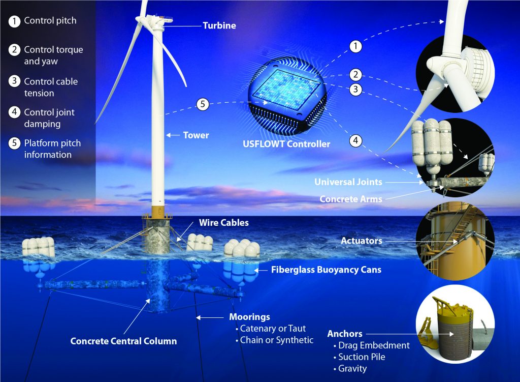
USFLOWT
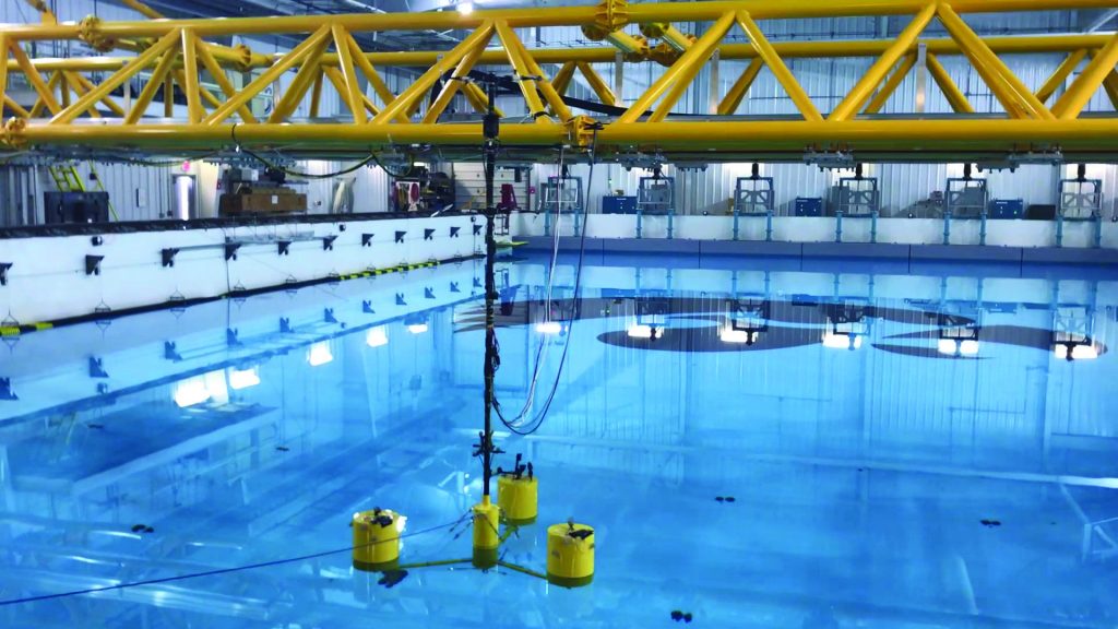
The design, known as the Ultraflexible Smart Floating Offshore Wind Turbine (USFLOWT) can be manufactured, assembled on site, and pre-commissioned, then towed to where it needs to be installed. The platform that hosts the turbine has been dubbed the SpiderFLOAT, since the system’s buoyancy apparatuses spread out from the center like a spider’s legs.
“The No. 1 thing — and this is true for all offshore structures — is you have waves, and waves induce motions, particularly if the structures are floating,” Sirnivas said.
Floating offshore systems usually consist of semi-submersible, TLP, or spar structures, according to Sirnivas. These systems have been adapted from the oil and gas industry, and there’s not a lot of difference for the wind industry other than the structure hosting a turbine.
“These structures are all pretty much rigidly connected, and with waves acting on them, the structure starts to move, the wave-induced loads are then taken up by the entire structure, and you have to design for it,” he said. “Without introducing flexibility, structural members are designed to carry all the loads resulting in a heavier system. In the offshore oil and gas industry, for example, wave-induced loads can be relieved by making the system a little flexible allowing for structural components to be lightweighted.”
The Ultraflexible Smart Floating Offshore Wind Turbine (USFLOWT) can be manufactured, assembled on site, and pre-commissioned, then towed to where it needs to be installed. (Courtesy: NREL)
Needed Flexibility
To make the structure lightweight, it must allow for some flexibility, which, in turn, allows things to move, according to Sirnivas.
“That’s what the SpiderFLOAT platform — the USFLOWT (SpiderFLOAT with a multi-megawatt turbine) for the ARPA-E project — we have is about,” he said. “It allows some of the wave loads to be mitigated, so it’s not transferred to the entire system. Then, we can lightweight the structural components, and that’s the primary reason, to mitigate the wave loads.”
With a rigid system, waves loads cause the entire structure to pitch back and forth. Active ballasting can be used to maximize the energy captured by actively ballasting/de-ballasting the buoyancy tanks with seawater to keep the system as upright and stable as possible, taking the mean pitch out of the system. It’s still going to pitch back and forth, but from a smaller initial pitch angle in order to capture more energy. The issue with active ballasting is the response time for controls, since pumping seawater in and out of the buoyancy tanks takes considerable adjustment time.
Quicker Reaction
With the SpiderFLOAT system, cables with tensioners are used, which can react a lot faster than active ballasting, where seawater is pumped in and out, according to Sirnivas.
“Our intent is to use these cables by changing the tension to take the mean pitch out and upright the system for improved energy capture,” he said.
Sirnivas, who brings to the table more than 20 years of working with the oil and gas sector, has used his expertise to adapt floating systems used in oil and gas for wind energy.
The oil and gas industry uses one-off traditional semis, spars, and TLPs. One of the main topics to address in wind is serial production, according to Sirnivas.
“You’re not going to build one; you’re going to build 10 or even hundreds of them for a given site,” he said.
Reducing Production Costs
Any type of offshore operation can get very expensive, very quickly, so Sirnivas said anything that can be done onshore, quayside, and near-shore is going to help reduce the overall cost.
Materials is another avenue the project takes advantage of to cut costs.
Whereas many offshore structures are made of steel, the SpiderFLOAT uses mostly concrete, according to Sirnivas.
“Concrete is cheap compared to steel, and concrete is also heavy compared to steel,” he said. “You want all the heavy stuff in the bottom — just like a sailboat with the keel on the bottom — to provide a restoring force for stability. What we have done in our design is similar: keeping the heavy components made of reinforced concrete at the bottom and the lighter buoyancy tanks made of fiberglass above. I call this ‘material use for purpose,’ addressing stability while reducing cost.”
With the SpiderFLOAT system, the legs are connected with universal joints to the central stem on one end and bundled buoyancy tanks on the other. The stem and the legs are made of reinforced concrete. The bundled buoyancy tanks are made of lightweight fiberglass, according to Sirnivas.
“If you look at the construction techniques that we have today, it is easy to pour concrete anywhere,” he said. “With the traditional steel semi, there’s a lot of cutting and welding involved. But with concrete, you can pour them onsite in a single piece. The buoyancy tanks could also be filament wound onsite. The entire system (platform, tower, and turbine) can be assembled and pre-commissioned at port with the onsite manufacturing to minimize the CapEx cost.”
NREL LDRD Funding
The advanced SpiderFLOAT design that was awarded a patent was a Laboratory Directed Research & Development (LDRD) at NREL that spanned more than two years. Sirnivas and his team were to innovate a new cost conscious floater design for wind turbines, which required “out-of-the-box thinking.” The team assembled a list of floater design functional requirements for the U.S., which generated various concepts. Further studies via computer modeling and simulations narrowed it to a single design: the SpiderFLOAT.
The advanced SpiderFLOAT design that was awarded a patent was a Laboratory Directed Research & Development (LDRD) at NREL that spanned more than two years. (Courtesy: NREL)
Energy I-Corps
The team then continued by participating in the Energy I-Corps program to understand the market and the pain points from the offshore wind-energy industry by conducting more than 70 interviews, which Sirnivas said was tedious, but necessary, for addressing concerns with the design — making it modular and to offer a turn-key solution.
The research continued with additional TCF funding for a scale-model test at the University of Iowa’s wave basin to study the performance of the system, which is a small part, but an important one, to start the de-risking effort, according to Sirnivas.
ARPA-E Atlantis Phase One
Sirnivas said the ARPA-E Atlantis phase one award was a blessing to mature the design using a control co-design (CCD) approach. The team introduced platform actuation to control the platform behavior in-sync with the turbine control to optimize the SpiderFLOAT platform for a 10-MW turbine called the USFLOWT-10. The objective was to achieve an LCOE of 7.5 cents/kWh.
Working together with the American Bureau of Shipping (ABS), Colorado School of Mines, the University of Colorado, and the University of Virginia, the team was able to increase the annual energy production via controls, according to Sirnivas. In addition, gaining the Approval-In-Principle from ABS was a key achievement for the design. The design has continued to evolve from the lessons learned in the wave basin test and the ABS roadmap to address redundancy.
“Instead of having three legs and three mooring lines, we now have six legs and six mooring lines to address a single line failure, improving stability with the buoyancy modules that are more evenly distributed,” he said.
ARPA-E Atlantis Phase Two
The next step is phase two.
“We are one of the fortunate few moving to phase two,” Sirnivas said. “The scope is being defined with the focus on further de-risking the technology, to eventually showcase the advantages and engage the industry.”
Eventually, this research will involve a comprehensive model test that would sidestep what Sirnivas calls a “subscale” design.
“I’m not a big fan of the subscale 20-kW designs in an uncontrolled, open-water environment for many months or even a couple of years, which is in the $10 million-plus range, because in the end, it just goes to the graveyard; nothing happens to it,” he said.
“We’re planning for a bigger-than-usual model test built of the full-scale materials and model-predictive controls for the platform and turbine in the next phase under a controlled environment collecting pertinent information to validate numerical models. This will be used to build a toolset for rapid design and re-engineering given a site and turbine size, and then we’ll approach the industry, particularly the wind-turbine developers, to get them engaged.”
Already, Sirnivas said there is growing interest within the industry about the technology, but he emphasized that the goal is not to rush the results.
“There’s been lots of interest, but our primary responsibility is to de-risk the technology first,” he said. “We also need to make sure that this actually adds value and addresses the industry pain points. We’re first going to prove and show the industry that the technology works, and then outline the value proposition. The thing about the ARPA-E Atlantis program is it’s a control co-code design effort. Traditionally, you would see floating offshore wind-turbine systems are designed to pass information back and forth between the floating platform designer and the turbine manufacturer. The reason being the turbine control algorithm are proprietary and specific to the turbine — they don’t want you to mess with it.”
Independently Designed
Hence, the platform and the turbine are not designed together with the ability to change the control algorithm during the design process (co-design), according to Sirnivas. They’re designed independently and then brought together for a semi-optimal design.
“The objective of ARPA-E Atlantis is to control co-design of the entire system,” he said. “In the USFLOWT, we control the turbine by controlling the torque and blade pitch, and we also control the platform with the actuators changing cable tensions, so it really becomes a control co-design problem. How do you use the controls of the turbine and controls of the platform to minimize the motion and to lightweight the system so we can hit the LCOE target set by ARPA-E Atlantis?”
The meticulous research will push the next phase of the project into four years before a full-scale model of the technology can be tested, but that will show the many efficient ways in which the USFLOWT system can help streamline the burgeoning floating offshore wind sector, according to Sirnivas.
“One of the functional requirements that we had in the very beginning is modularity,” he said. “Accommodating larger, heavier turbines with bigger thrust will not require complete re-engineering of the USFLOWT. So, how do we accommodate? Currently, for the USFLOWT 10 MW, we have six legs, and on each leg, we have three buoyancy tanks. For larger turbines, we extend the legs a little, and add more buoyancy tanks — simple.”
Because of the design’s modularity, it is able to accommodate turbines from 6 MW up to 25 MW, according to Sirnivas.
The interests in the technology is encouraging since there are many offshore areas in the U.S. that could benefit from the USFLOWT design.
Sirnivas said companies with leases off the West Coast of California have shown interest in the design, where it would be beneficial, but other areas could also benefit, including Hawaii, the Gulf of Maine, and the Gulf of Mexico — all deep-water sites with good wind resources.
Reygar, a vessel monitoring and control solutions provider, has won InnovateUK funding to develop a range of new features for its BareFLEET product in collaboration with Singapore-based designer, builder, owner, and operator of high-speed aluminum craft, Penguin International Limited.
The project, dubbed FleetVision, will build on Reygar’s BareFLEET technology to offer live feedback on aspects of vessel performance, leveraging Penguin’s experience in shipbuilding and ship management.
Machine learning tools will be jointly developed to identify operating efficiency and cost reduction opportunities and to monitor machinery health, alongside adaptations that will enable more vessel types to benefit from the system.
Penguin designs and builds a range of aluminum workboats that it also owns and operates. Since 1995, Penguin has delivered more than 200 aluminum vessels to ship owners and is the world’s biggest builder of multi-role crew boats.
Both Reygar and Penguin envisage long-term, mutual benefits, with the project acting as a potential launch pad for access to new technology and target markets.
James Tham, Penguin’s managing director, sees potential in the application of data-driven performance monitoring technology to enhance efficiency and emission reductions for commercial high-speed vessels.
“FleetVision represents the coming together of proven expertise and experience in real-time remote monitoring technology and the design, construction and operation of efficient, human-centric high-speed workboats,” he said. “The outcome will be an intelligent performance analytics and decision support tool, developed by experienced practitioners, for sustainable high-speed vessel operations.”
“We are passionate about helping fleet operators make better, more informed decisions to reduce fuel consumption and emissions,” said Reygar CEO Chris Huxley-Reynard.
“Live feedback on vessel performance means that a range of cost, fuel and emissions saving opportunities can be seen and acted upon in real time, optimizing operations both onboard and from the shore. Leveraging machine learning to help identify trends in machinery health and vessel performance also improves availability and supports the achievement of perating efficiency goals.”
US Critical Materials Corp. recently announced the highest reported total rare-earth oxide grades (TREO) of any rare earth deposit in the United States at the Sheep Creek deposit in Montana. The levels have been confirmed by analyses from Activation Labs, an independent analytical laboratory in Ancaster, Canada.
“We have confirmed that Sheep Creek is the highest-grade rare-earth deposit in the United States, with a multibillion-dollar resource value,” said Jim Hedrick, US Critical Materials president and former rare-earth commodity specialist at the U.S. Geological Survey (USGS).
US Critical Materials has nearly 9 percent TREO (89,932 ppm), far ahead of any other domestic rare earth resource. The deposit also has readings of 2.4 percent (23,810 ppm) combined neodymium and praseodymium, which are both essential for the green economy.
US Critical Materials has recently confirmed carbonatite mineralization at depth, below high-grade surface samples of 17.05 percent TREO and 16.44 percent TREO. The Sheep Creek, Montana, property under claim by US Critical Materials totals seven square miles.
For context, the Swedish government announced on January 12, 2023, that a Swedish state-owned mining company had discovered Europe’s largest deposit of rare earths, with an average grade of 0.18 percent TREO.
US Critical Materials’ goal is to supply consumers, industry, and the U.S. government with the critical minerals required to meet technology, manufacturing, and defense needs, with the overall objective of addressing the necessity to obtain rare earth materials from “friendly” sources as defined by the Inflation Reduction Act (IRA). The United States is more than 90 percent import-dependent on rare earths, most coming from China.
The Sheep Creek claims contain 12 of the most essential critical minerals needed for the world’s evolution toward electrification and a “green economy.” In addition to their high rare earth levels, the claims are particularly low in radioactive thorium, thereby shortening the permitting process.
US Critical Materials is working with a national laboratory to develop efficient and environmentally safe processes for domestically refining the rare earths found at Sheep Creek.
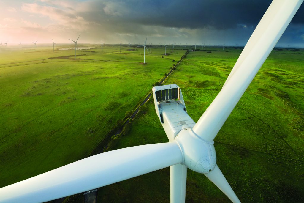
Planning law changes proposed by the U.K. government lack measures that aid larger onshore wind projects and national targets are needed to make stakeholders accountable, project partners told Reuters Events.
The U.K. government in December said it would ease restrictions on building onshore wind farms in England after objections by 34 MPs from the ruling Conservative party.
The U.K. operates 15 GW of onshore wind capacity, and development activity has mainly been confined to Scotland since rules in England were toughened by David Cameron’s Conservative government in 2015. Much of Scotland benefits from windier conditions and larger areas of unpopulated land but electricity demand is higher in England.
Large wind farms offer lower energy costs but there are relatively few in England. (Courtesy: Reuters)
In a U-turn by Prime Minister Rishi Sunak, the government said it would adapt the National Planning Policy Framework to permit onshore wind development where local consent is demonstrated and any impacts identified by the local community are appropriately addressed. Previous rules meant opposition from one person could block the project, despite government surveys showing 80 percent of the public were in favor of onshore wind farms.
The details of the reforms will be established through a public consultation that will conclude in April and will also seek views on how local communities could benefit from the projects through lower energy bills.
Further reforms are needed to support larger onshore wind projects as the proposed changes are likely to mainly aid smaller, community-scale projects, wind farm developer RWE told Reuters Events.
Turbine supplier Siemens Gamesa welcomed the reforms but called for the government to set national onshore wind targets that include planning milestones. Prior to the reforms, industry group RenewableUK targeted 15 GW of new onshore wind capacity by 2030 but only 1 GW in England.
The government is already reforming planning rules for offshore wind as it looks to quadruple capacity to 50 GW by 2030. “It’s important that planning constraints are part of the progress tracking as they already hinder offshore progress,” a Siemens Gamesa spokesperson said. “We should use our combined and substantial knowledge to improve these lead times.”
What is Energy Shares and what does it do for the renewable energy sector?
Energy Shares is a FINRA registered broker dealer. Energy Shares brings together renewable energy developers and retail investors through an equity crowdfunding platform.
Working together, we can raise the needed capital to accelerate and scale the renewable energy market in the U.S.
What is your role with Energy Shares?
I am the CMO and run all aspects of marketing for the company.
Energy Shares recently conducted a study on renewable energy. What takeaways were discovered?
Some of the key takeaways are that the market opportunity around renewable energy continues to grow. With investment coming from the federal government through the Inflation Reduction Act, along with the increasing demand by consumers for electricity, and the growth projections for new renewable energy utility scale projects over the next five years, this creates a need for scale and acceleration. Solar and wind projects are the most commercially viable solutions for utility scale projects today and can include a storage component. Overall, there is a push to launch more projects, given the time factors before they can be brought online, producing electricity.
Since our readership is primarily for the wind-energy sector, what makes clustering wind turbines more cost effective?
One of the key items with clustering is that now the entire deployment of wind turbines can act as a single producer of electricity with a single sub-station connecting into the grid and transmission lines. You can also layer in battery storage to further capture and store the newly generated electricity into a single location. So, clusters function more like a centralized plant vs. a distributed plant. Overall, you are reducing maintenance points and connection points while centralizing the power creation. And this allows for great scale in terms of output volume for a given wind farm.
How is Energy Shares going about bringing renewable energy developers and retail investors together?
The United States is in the process of moving from fossil fuels to renewable energy sources combined with an increase in demand for electricity by consumers and businesses. With more electronic devices, EV cars and batteries, and electrical appliances on the market, the need for electricity is only increasing. But where does all the production of this electricity come from today? It still comes from fossil fuel and natural gas production plants. So, all of this new green tech is still being powered by fossil fuels.
From an investment perspective, over $50 billion flowed into EV technology, battery technology and manufacturing, and chargers and charging infrastructure in 2022. What is still needed is investment in the actual production of electricity. All behind the scenes.
The talk of solar and wind farms is only growing, but you cannot just find some land and start installing solar panels or wind turbines. It can take several years to get the needed permits, land rights, and determine the optimal construction plan before breaking ground — this is known as “development.” And right now, solar- and wind-farm developers across the country need the financial resources to enable the future construction of these renewable energy electricity power production capabilities. This creates an investment need and opportunity. Energy Shares provides the platform to bring developers and retail investors together.
What are the advantages to having individual investors crowdfund projects?
The key here is to enable retail investors to have the opportunity to directly invest in development stage renewal energy projects here in the U.S. Retail investors up to now had limited ways that they could participate in this market. Consumers are seeing and reading all the media coverage talking about the renewable energy market and how the Inflation Reduction Act (IRA) is promoting renewable energy. Energy Shares provides a platform for retail investors to learn about the industry and to decide if they want to participate in these projects. For renewable-energy developers, this is a new mechanism for them to be able to raise the needed capital for their projects.
How soon do you see the results of the study being applied to real-world projects?
We are hoping to see results applied into projects later this year. But as we know, projects in the development stage can take several years to be ready for construction and eventually generate electricity.
So, the key is to help launch development projects and get them into the queues so that in the coming years they can begin producing electricity.
Using the study’s findings as a guide, where do you see the renewable energy sector — particularly wind — in the next 10 years?
We see wind and solar as the most commercially viable renewable energy solutions that can scale and accelerate the production of electricity using renewable energy. So, as developers launch new projects today, over the next three, five, seven years, these projects will be built and come online producing electricity for the country.
When it comes to renewable energy initiatives, HEICO doesn’t just talk the talk. It walks the walk.
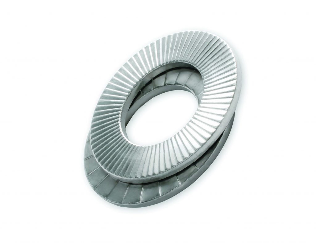
The German-based company has not only been manufacturing an innovative wedge-lock washer used in wind turbines, but it has also made great strides over the years to reduce its carbon footprint.
HEICO’s state-of-the-art facility in Germany might be considered a model of sustainability, according to Luke Reed, sales manager, North America. HEICO has built a custom thermal power plant onsite, which also provides power to the company and the surrounding communities. And recently, the company has implemented an application that captures heat waste from its coating process and uses it to warm the water for manufacturing. The company also has a solar-power array on its roof that provides additional power to the facility. But it doesn’t end there as HEICO is looking into investing in its own wind farm in the near future.
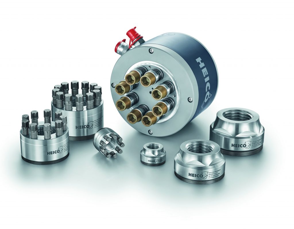
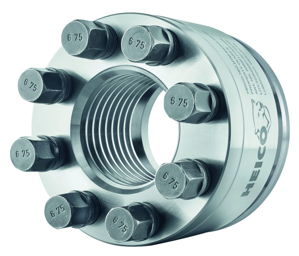
HEICO-TEC Tensioning Systems make up an easy, fast, and reliable assembly of large bolted joints. (Courtesy: HEICO)
So, to say HEICO has gone “all in” for a sustainable future might be an understatement — so much so, that what the company actually does for the wind-energy industry might be an asterisk on its resume, but it is an extremely important asterisk.
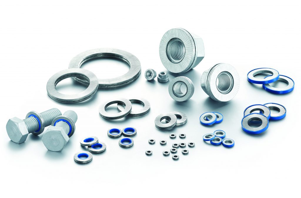
“As far as the wedge lock washer goes — the HEICO-LOCK line — it is a marvel of modern engineering,” Reed said.
Critical Joints
Thousands of bolted joints in a wind-tower nacelle all work in tandem to piece the machinery together; many of those are deemed critical to the safety and performance of the asset, according to Reed.
“The failure of a single bolt can quickly spread to the adjacent bolts,” he said. “On one end you’ve got, due to a bolt failure, power generation stoppages, and on the other end you’ve got huge safety potentials with capital costs and ceasing of revenue, but more importantly, ceasing of power production. That can even lead to — and fortunately, it’s rare —even injury and loss of life. So, we really take the wind category very seriously because the critical bolted joints there are certainly critical for a good reason.”
Wind turbines generate a lot of vibrations, and a lot of different loads can affect the bolted joints securing the clamped parts, according to Reed. The wedge lock washer is designed to address these types of potential problems in a functioning wind turbine.
“They simply really, really work well to address the concerns that these design engineers have on a day-to-day basis,” he said.
How it Works
The wedge lock washer is a two-part washer system based on the fundamentals of tension, according to Reed. The washer is designed around a certain geometry on the inside surface that, once the bolt is torqued down, the ramps — or wedges — engage.
“Whenever that bolted joint is being influenced, say by intense vibration, in a traditional sense, it wants to start rotating and come loose,” he said. “Those wedges are angled in a way that prevents that bolt from turning. Basically, it’s impossible for that bolt to come loose. And, in fact, as it’s being hit by very high shock loads, for example, as the bolt wants to turn, it’s actually getting tighter. It’s a fascinating and very elegant solution.”
This ability to actually self-tighten can be a critical function when bolts are needed in tight spaces — a situation that is very common within a turbine nacelle, according to Reed. In addition to its innovative washer, HEICO also has developed the HEICO-TEC mechanical tensioner to aid in tightening hard-to-get-at bolts.
“Today, you have hydraulic and pneumatic type tensioners — big tools that certainly have their place — but what happens is, in areas of confined spaces where you’re doing a repair job or a refurbishment, it’s really hard sometimes to get these torque tools to bear onto a bolted joint,” he said. “For example, with a two-inch bolt, you’ve got a relatively high torque value to tighten that bolt correctly. With the HEICO-TEC mechanical tensioner, it breaks that large torque value down into multiple smaller torque values that you can operate with just a simple torque wrench. And if an operator can get a handhold into that very confined space, he can tighten the largest bolt that a wind turbine could potentially have.”
HEICO has developed the HEICO-TEC® Multi-Tool that allows the simultaneous tightening of all the pressure bolts without any additional force being required by the installation personnel. (Courtesy: HEICO)
Industry Takes Notice
HEICO’s wind products have certainly caught the eye of OEMs in the 13 years the company has offered them, according to Reed.
“The influence and the proficiency of our engineering staff in Germany has grown to the point where it’s not uncommon for an OEM or an owner-operator to actually reach out to us looking for some guidance on bolted joint issues or bolted joint designs for future applications,” he said.
The overall industry interest in HEICO’s product line comes down to the fundamental idea that drives the company: quality you can depend on, according to Reed.
“That means the fasteners or any component of a wind turbine we make simply needs to perform as it was designed, and it needs to be entirely dependable, and there can be no exceptions,” he said. “There’s just too much at stake.”
That, Reed said, boils down to common virtues from the HEICO Group that can be seen from the owner through senior managers all the way down to apprentices just starting their HEICO journey. Those virtues are innovation, discipline, reliability, punctuality, precision, and efficiency.
“Those are virtues that are often discussed, and we base a lot of our outlook on doing business and dealing not only with our customers in the industry, but dealing with our people,” he said. “I think our customers who have spent time with us and have visited our location in Germany all tend to get that pretty quickly and reward us due to that increase in confidence.”
And those inherent virtues circle back to how HEICO is involved in sustainability from top to bottom, according to Reed.
HEICO-TEC Tension Nuts in strength class 8 and 10 meet all the requirements of ISO 898-2. (Courtesy: HEICO)
“You hear sustainability, and a lot of times it’s kind of a check-the-block statement; it’s not backed up by practice,” he said. “But for the HEICO Group, this is certainly a guiding principle, and not only in terms of the markets that we serve — wind being this great example — but in terms of energy use and conservation and efficient manufacturing practices.”
123-Year History
Although HEICO has only been involved with the wind industry since 2010, the family-owned company — currently run by Jan Heimann — has been around for 123 years in western Germany where it began as a cold-forming parts manufacturer. In the beginning, HEICO was primarily involved in agricultural implements, food production, and parts for furniture manufacturing.
Over the last century, the automotive industry fueled a lot of HEICO’s growth making cold-formed parts. As the company grew and built up its engineering prowess in terms of quality manufacturing, processes, and design, HEICO obtained its ISO 9001 certified manufacturing status in the 1990s. Shortly after that, HEICO received its IATF 16949 quality certificate, which offered a lot of parallels with the APQP4Wind quality process. And most recently, HEICO acquired its ISO 14001 certification.
In 2010, a globally recognized fastener supplier came to HEICO, asking if the company could make a bolt securing element. That eventually evolved into the wedge lock washer.
“So, when we first developed the HEICO-LOCK wedge lock washer series of products, the demand was immediately there — it took off; it really took off incredibly well,” Reed said. “At the beginning, our focus in terms of industrial categories was the rail industry, both on the ground and up in the cars, and then in power generation markets.”
Industry Expansion
The product exposure quickly expanded to other industries, and then, shortly thereafter, the HEICO-TEC mechanical tensioning line was developed.
“Today, at HEICO, we’ve got 14 company-owned subsidiaries around the world,” Reed said. “And the North American subsidiary here in Hickory, North Carolina, was started in 1997. We don’t manufacture anything here, but we do the sales and engineering and inventory support to our customer base.”
Worldwide locations coupled with 123 years of expertise have put HEICO in a unique position to take on any challenges the company’s customers may throw its way, according to Reed.
An important feature of HEICO-LOCK Wedge Lock Washers is the securing of the bolt fastening using preload force rather than friction. (Courtesy: HEICO)
“Our engineering know-how has reached a point where we’ve got an extremely robust and innovative engineering staff in Germany; these guys live to be presented with a problem or a potential issue with a future design,” he said. We’ve got a lot of smart and dedicated engineers both at the beginning of their careers as well as senior veterans who have been doing this for many, many decades.
So, when a customer comes to us, the collaborative spirit that HEICO has is apparent. From engineering, quality, manufacturing, sales, marketing, and commercial — all these different departments — if you were walking the halls of HEICO Group today in Germany, the collaborative spirit that we have with finding solutions to a customer’s bolted joint situation would just jump out at you. At the end of the day, we always stress: Bring us your situation, and let us improve it.”
As the wind sector continues to grow and mature, especially offshore, Reed said HEICO will continue to offer its innovative technology wherever it may be needed.
“The driving factor is corrosion and longevity; a bolt and a nut and any securing elements you use simply have to maintain a given requirement in terms of corrosion resistance; a critical bolted joint on a wind turbine can’t fail,” he said.
“And a bolted joint that’s secured with a HEICO-LOCK wedge lock washer simply cannot fail. That’s something that we’re very proud of.”
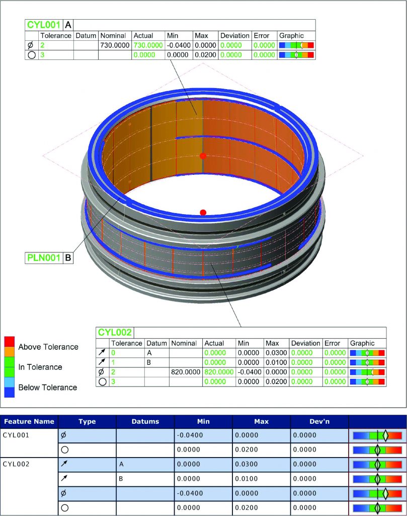
Recently there has been a significant increase in demand for larger bearings up to 1,200 mm in diameter for use in the construction of wind turbines, which promises exponential growth in the coming years as countries across the globe work toward meeting their green energy targets.
In addition to the wind energy sector, the Dudley, U.K., factory of The Timken Company supplies the engineered bearings it manufactures into a multitude of industries including mining, food and beverage, pulp and paper, cement, marine, and wastewater.
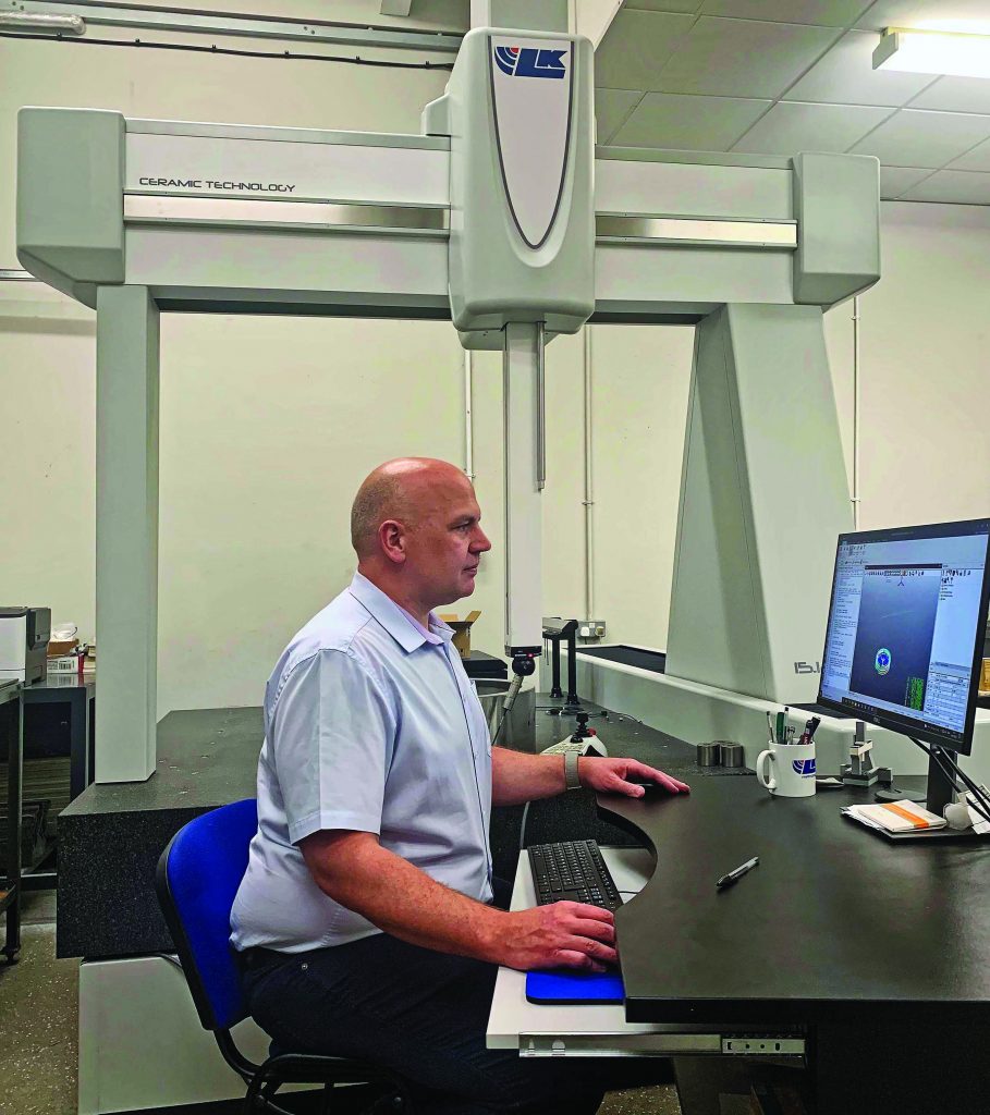
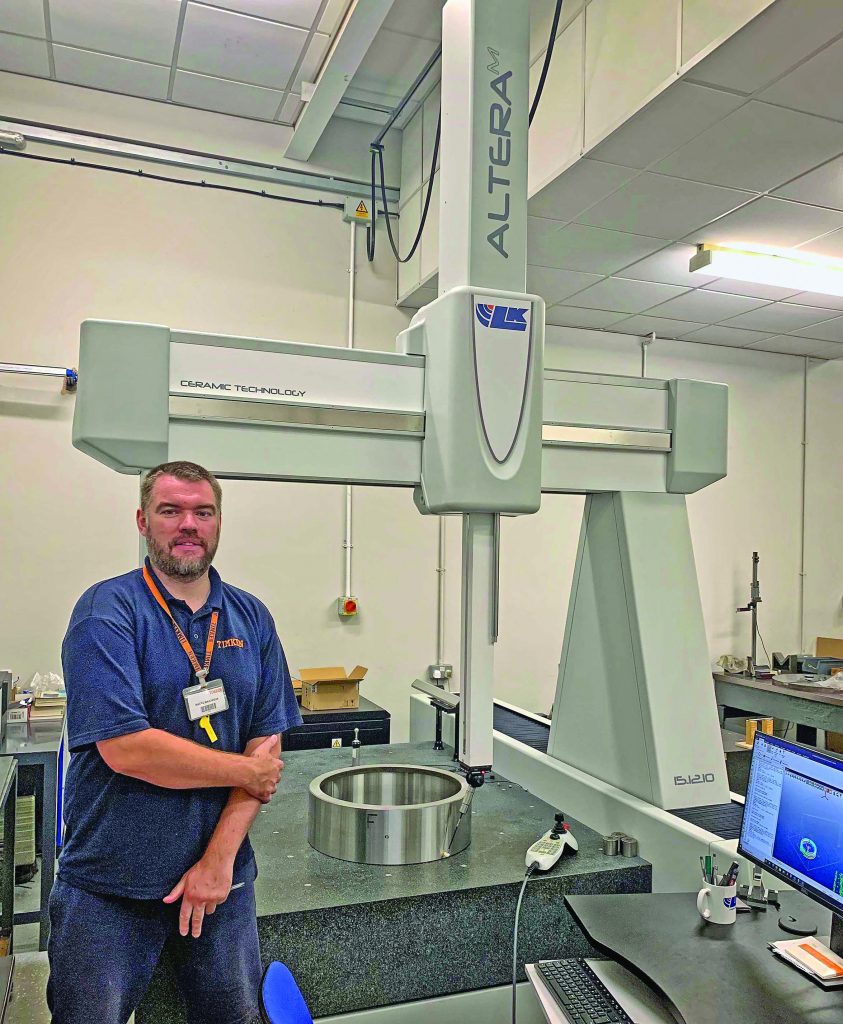
William Hayes, quality improvement engineer at the Dudley factory of The Timken Company, with the new LK Metrology AlteraM 15.12.10 ceramic bridge coordinate measuring machine. (Courtesy: The Timken Company)
To enable the company to inspect these larger bearings needed for wind, Timken purchased an AlteraM 15.12.10 ceramic bridge coordinate measuring machine (CMM) with axis travels of 1,500 x 1,200 x 1,000 mm manufactured by LK Metrology Castle Donington. Assisting further in Timken’s quality control department is a Mitutoyo CMM capable of measuring ball and roller bearings with bores up to 800 mm in diameter. This machine was upgraded at the same time by LK with a new controller and identical CAMIO 2021 software for measurement, programming, analysis, and reporting, so inspectors are able to swap programs conveniently between both machines.
Checking Features
Dozens of high precision geometrical features need to be checked on each bearing to ensure that flatness, circularity, radial run-out, and track width meet specified tolerances, some of which are within ±6 µm. This is achieved quickly, repeatably, and automatically on the CMMs at Dudley in computer-controlled cycle times of about 10 minutes.
“We selected LK Metrology to provide the new inspection facility, as it was the only potential supplier to offer us a new, well-priced, high accuracy machine of the right capacity,” said William Hayes, quality improvement engineer at the Dudley factory. “The company was also proactive in offering to retrofit new control software to our Mitutoyo BN710 CMM, as we need two measuring machines to cope with our increasing production throughput.”
“Another point in LK’s favor was that its CMMs are installed in Timken plants in other parts of the world, including in the U.S., so the supplier was not an unknown quantity,” he said. “It would, in theory, be possible to exchange programs internationally, but, in practice, this is unlikely to happen as most of our other sites are mass production environments, whereas we specialize in producing small quantities of engineered bearings below 10-off.”
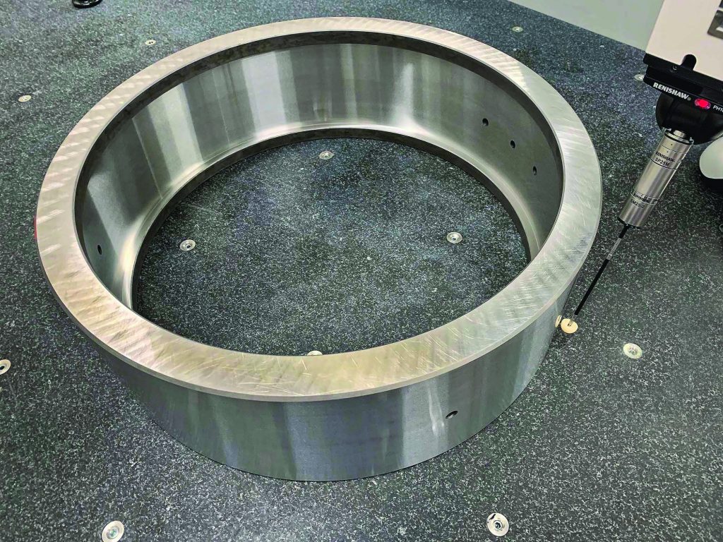
Maciej Majchrzak, Quality Inspector, inspecting a Timken engineered bearing outer race. (Courtesy: The Timken Company)
New Technology
Hayes explained that LK also supplied new technology in the form of a Renishaw PH10MQ motorized tilt and rotate head and SP25M scanning probe with interchangeable styli. Together they are able to take measurements at important discrete points, as previously, or to scan large areas very quickly. For example, the system is able to scan a circle at 1.2 m/min, acquiring up to 1,000 measurement points every second as it does so. An additional benefit of the SP25M probe is the possibility to accurately measure with stylus lengths up to 400 mm, allowing awkward areas of a component to be reached, whereas there is a stylus length limit of 100 mm with traditional probes from Renishaw.
The change in functionality from touch trigger probing to scanning is fully programmable. In the case of Timken’s cycles there is approximately a 50:50 split between the two modes of operation. They are performed by the SP25M probe, as there are two sensors built into the single housing, so there is no need for probe exchange. The wealth of data obtained is able to provide a very accurate report concerning deviations in size, position, profile, and form that can affect bearing performance. Higher speed inspection also enables metrology to provide prompt feedback for adjusting production processes.
Bearing outer race inspection in progress by touch probing and scanning in a single 10-minute cycle. (Courtesy: The Timken Company)
Quick Training
Within 10 days of the new CMM installation at Dudley and the simultaneous upgrading of the smaller machine, two of Timken’s six inspectors had already undergone training by LK Metrology engineers and were checking bearings on both CMMs. The latest version of LK’s CAMIO 2021 software has the advantage of helping to increase inspection productivity, enhance the quality of data collected and gain better insight into the components being measured. New inspection programs are prepared quickly by automatically detecting which surfaces of the CAD model should be used to measure a feature. Improvements have also been made to the programming workflow by extending the advanced picking function to touch points and scan paths on a CAD model and to indicate the selection of existing measured features.
About The Timken Company
The Timken Company designs a growing portfolio of engineered bearings and power transmission products. With more than a century of knowledge and innovation, it continuously improves the reliability and efficiency of machinery and equipment to move the world forward. Timken posted $3.5 billion in sales in 2020 and employs more than 17,000 people globally, operating from 42 countries. Timken is recognized among America’s Most Responsible Companies by Newsweek, the World’s Most Ethical Companies® by Ethisphere and America’s Best Employers by Forbes.
About LK Metrology
LK Metrology is renowned for innovative metrology solutions and services. The company’s products, including coordinate measuring machines (CMM), portable measuring arms, and metrology software, are used worldwide to control and improve the quality of manufactured components. Its precision technology underpins the process chain from design, development, production and assembly through to quality assurance in global industries such as automotive, aerospace, defense, motorsport, energy, medical, and contract inspection.
A typical quality report automatically generated in LK CAMIO 2021 after inspection of a Timken bearing. (Courtesy: The Timken Company)
Established in England in 1963, LK Metrology has an impressive heritage in metrology dating back to the birth of CMM technology. Founded by CMM pioneer Norman Key and his father-in-law Jim Lowther, LK Metrology is credited with many of the CMM industry’s firsts including the first bridge-type design, first OEM to integrate computers, first to use a touch trigger probe, first to develop inspection software, first to use all air bearings and granite guideways, first to use carbon fibre composite spindles, first to use microprocessor-controlled drive systems, first to produce a truly thermally stable CMM and first to produce a high-accuracy horizontal-spindle CMM.
In 2018, LK Metrology was relaunched as an independent CMM manufacturer after several years as a division of Nikon Metrology. Headquartered in the UK, LK’s CMM development and production are at the company’s facility in Castle Donington. Sales and support offices are located in the UK, North America, Belgium, France, Germany, Italy, and China, supplemented by a worldwide distributor network.
Cranes, wind-turbine blades, and airplane wing flaps all have a similar problem: The bearings that help them rotate don’t go in a full circle. Like kids on a swing or seesaw, they oscillate back and forth or up and down.
Some oscillating bearings also can be thought of as carrying a load rather than rotating a device, said Mike Chartre, CEO of Powertrain Engineers, a company that designs industrial gearing shafts and bearing systems.
“It’s a static bearing being used for position, not for rotation,” he said. “It’s transmitting a torque, typically when you have an application like wind-turbine blades. It’s like a Lazy Susan bearing on your spice rack that you turn to the position you need. The purpose of the bearing isn’t so you can spin it around in circles.”
Spinning Lazy Susans aside, with so many cycles happening in applications that don’t lend themselves to easy replacement, understanding this motion and the damage it can cause is critical to predicting an accurate lifetime for bearings in oscillating applications. Not only is this type of motion severe and demanding but so is the starting and stopping as the rotation reverses.
Some turbines have automated systems that can tell when the wind dies down enough to give blades a good twist, just to spin the bearing every so often. (Courtesy: STLE)
“The standards of the bearing world are all set up around the full rotation of a bearing; there are changes to those calculations that happen with oscillatory motion,” said Ian Hegner, manager of research and development at Rexnord Corp., a company that designs applications for the airplane industry such as wing and tail flaps.
Design engineers looking to determine the lifetime of rotational bearings use analyses from 1947 that made the basis for a 2007 standard known as ISO 281 [1]. Since then, engineers have developed modifications to that standard that consider oscillations rather than full rotations, but different assumptions and approaches overestimate lifetimes or fatigue, and the size of the oscillation also must be taken into account [2,3].
Also, conditions in real life aren’t usually ideal. In an analysis in 2018 of a crane winch [4], the authors pointed out that unlike that kid on the swing, real oscillations in the crane are imperfect and bumpy rather than a smooth sine curve. The approximations differ enough from reality that the equations might be overestimating the lifespan of oscillating bearings.
Angling Toward Lifespan
Lack of big movement damages bearings in propellers, turbines, and other applications slowly and indirectly. For example, in a 2018 computer simulation of a wind turbine, researchers showed that the pitch bearings — the ones that let the blades twist on their long axes to catch the right amount of wind — are at risk of surface-induced damage by oscillating between 0 and 2.5 degrees for about 127 successive days over 20 years [5].
“While they’re not spinning around in the traditional sense that you think of in a bearing, the bearing elements have little movement and potentially a ton of force,” Chartre said. “And if it just moves back and forth a little bit, eventually it’ll evacuate all the grease out of the raceway. And once the grease is gone, there’s no film to protect the surfaces from adhesion. So, on the microscopic level, you get really high loads and, potentially, welding of the two surfaces together for an instant. And then it breaks apart when there is movement. That can happen over and over, and eventually you get degradation of the surface. That’s called fretting.”
Engineers find that rotating bearings are a place to start to determine lifespan. The simplest way to determine the lifespan of bearings in oscillating applications is to sum up the distance the oscillations move, convert that total into full rotations, and use that in the standard ISO 281 [5].
“That’s something that everybody agrees on pretty universally until you get below that critical angle,” Hegner said.
Small angle oscillations create different damage conditions than full rotations. Rotational bearings are subject to rolling contact fatigue. They are rotating long distances (relatively) and at high speed under elastohydrodynamic conditions. But elastohydrodynamic conditions disappear with small amplitudes, slow speeds, and heavy loads. These conditions create surface-induced damage such as false brinelling and fretting.
Enter the critical angle, one of two relevant angles to consider to understand the damage modes. In seminal work as a lifetime member of ASME, the late John Rumbarger provided commonly used definitions: The critical amplitude of oscillation is defined as the angle of rotation of one race relative to the other race for which the race path stressed by one rolling element, such as a ball or roller, just touches but does not overlap the race path stressed by adjacent elements [6].
Another zone of operation called the dither zone is oscillation at very small amplitudes where the stressed area, or contact footprint between the element and the race, is only partially uncovered and then retraced [7].
“As you leave that critical angle and get toward the dither angle, it’s a whole different equation to determine the life of a bearing.” Hegner said. “And that’s the area that needs more attention, in my opinion, because the bearing world is more concerned about fatigue and whole rotation. These oscillatory application engineers are more worried about the wear piece of it, and that’s the more difficult piece to get your hands around.”
Barely Moving and the Damage Done
One way the simple back and forth movement going very small distances causes damage is by starving the bearings for lubrication. Small angles don’t push the grease around enough. And different amplitudes create different kinds of damage.
“If it’s a larger angle, which would be around the critical angle or larger, you may see metal-to-metal contact, and that would likely create surface-initiated spalling failure,” Hegner said. “And if it’s a small angle that’s closer to dither, that would be your fretting failure.”
“Other kinds of oscillations can cause damage as well,” said Ed Hahlbeck, CEO and owner of Powertrain Engineers. “In applications where the load is oscillating and the bearing is basically static, the wear occurs due to the changing contact position as load changes. Thus, very low internal clearance is critical, along with adequate support to keep races aligned.”
Lack of big movement damages bearings in propellers, turbines, and other applications slowly and indirectly. (Courtesy: STLE)
If the raceways and elements are starved for lubrication and grind past each other, they can create shallow ruts known as false brinelling. True brinelling deforms metal into pits or ruts, but false brinelling can involve some loss of metal. Under the right conditions, say if water gets into the bearings, these ruts can grow, deepen, and turn into fretting corrosion.
Another type of failure that doesn’t have to do with lack of lubrication, but with the hardness between, is rollers and raceways.
“If you have a really hard roller against a softer inner ring, and you just have the small back and forth movement, you can actually create a little groove in a deforming way,” Hegner said. “It’s kind of like fretting, but it’s wear due to a hardness differential.”
To counteract the potential damage, design engineers sometimes make the rolling elements cover more space.
“One way is to go for broader surfaces, using something other than just a ball,” Chartre said. “Cross roller designs are pretty common in these sorts of applications.”
The elements in cross roller bearings look like barrels. They’re tipped on their side 45 degrees, with the next one tipped the other way at 45 degrees. The roller touches the raceway along a length rather than on a point like balls do. For example, if you roll a ball along the ground, the ball touches the ground at one point. With a bearing, this forms a line in the middle of the raceway as the ball rolls. If you tip a barrel on its side and roll it on the ground, the whole length of the barrel touches the ground, from top to bottom. And so on the raceway, a roller bearing spans more of the raceway than a ball bearing, distributing wear more widely.
Some turbines have automated systems that can tell when the wind dies down enough to give blades a good twist, just to spin the bearing every so often.
Feeding Lubrication
Engineers discovered damage due to false brinelling, sometimes considered fretting, due to oscillations almost 100 years ago. Back in the 1930s, automobiles that shipped by train ended up with damaged wheel bearings. The vehicles were tied down on train cars, but they still jostled on the rickety tracks. Like Hahlbeck’s example of an oscillating load and a static bearing, the captive wheel bearings suffered from unwanted contact.
“To combat that, there are anti-fretting additives in greases, so you can modify the lubricant,” Hegner said. “In our industry and aerospace, our customers pick one or two different greases, and we’re at the mercy of what they pick.”
For today’s oscillating bearings, guidelines suggest, at a minimum, using grease with anti-wear and extreme-pressure additives [8].
Design methods are a possible way to disperse the lubrication throughout. Evenly spacing input points around the bearing and putting grease exit openings between them is one idea.
“In this way, the grease has a short distance to travel to cover the areas and can expel the residual grease nearby,” Hahlbeck said. “Often this type or application will generate some frettage debris, thus expelling used grease is critical.”
Rexnord designed a “precessing retainer” to make the elements move around the raceway, albeit slower than in rotational bearings. A slight tilt in the guide ring for the rollers moves the bearings “five steps forward and four steps back.” [9]
“It is sort of like a one-way clutch, but it doesn’t totally restrict movement,” Hegner said. “It moves easier in one direction than the other, and that will move the rollers all the way around the bearing, which will then in turn load all the rollers and then also load different areas in a ring. So, it just distributes that wear throughout the bearing.”
Hegner said the precessing retainers work well under small-angle applications.
“If we have an application that has a high amount of dither cycles, then we would recommend the precessing retainer when we design the part,” he said. “If it has a high amount of large angle oscillations, then we wouldn’t recommend it because it would create too much resistance in the motion. Under very small angles, plus or minus five degrees or less, it’s a successful type application. But if a significant amount of the application’s cycles are higher than five degrees, then the precessing retainer might become more of a detriment than a benefit.”
Another method is to just spin the bearing every so often.
“In the case of turbines, it is important to pitch the bearings or to execute a yaw movement to redistribute the lubricant,” Hahlbeck said. Some turbines have automated systems that can tell when the wind dies down enough to give blades a good twist.
“The primary direction of the wind is largely the same every day,” Chartre said. “But every once in a while, when the wind allows, they’ll spin the thing around 360 degrees one way and spin it back the other way.”
For applications in which the load is almost always in one spot, such as building cranes, crawlers, or mining shovels, remounting is a way to extend the life of a bearing. (Courtesy: STLE)
Future Spins
Advancements in greases, coatings, or surface treatments might be in the future to prevent damage to oscillating bearings or lengthen their life.
“I think we’re seeing more and more of the small angle applications in our industry,” Hegner said. “We’ve been very successful with the precessing retainer, but I think there are still more solutions out there.”
For applications in which the load is almost always in one spot, such as building cranes, crawlers, or mining shovels, remounting is a way to extend the life of a bearing.
Improved additives for greases would help some industries, although Hegner said the aerospace industry can be slow to adapt to new things because of safety issues.
Up in space, new coating or surface advancements would be better than ones in grease since greases don’t work due to a lack of oxygen. However, airplanes have very high loads that can crack away a coating.
Low-tech solutions also are out there. For applications in which the load is almost always in one spot, such as building cranes, crawlers, or mining shovels, Chartre suggests remounting as a way to extend the life of a bearing.
“One of the things that you can do on a manual application is if you have a bearing that is going to be oriented one way for most of its life, you could probably extend the use of that bearing by occasionally remounting it, so it’s now in a new position sharing a load somewhere else,” Chartre said.
“You could get really get clever and build a system to rotate the bearing, which is probably going to involve another bearing.”
REFERENCES
ISO (2007), “ISO 281:2007 Rolling bearings —Dynamic load ratings and rating life,” International Organization for Standardization. Available at https://www.iso.org/standard/38102.html.
Wöll, L., Jacobs, G. and Kramer A. (2018), “Lifetime calculation of irregularly oscillating bearings in offshore winches,” Modeling, Identification and Control, 39 (2), pp. 61-72. Available at https://www.mic-journal.no/ABS/MIC-2018-2-2.asp/.
Ibid.
Stammler, M., Reuter, A. and Poll, G. (2018), “Cycle counting of roller bearing oscillations – case study of wind turbine individual pitching system,” Renewable Energy Focus, 25, pp. 40-47. Available at https://www.sciencedirect.com/science/article/pii/S1755008417302624.
Harris, T., Rumbarger, J. and Butterfield, C. (2009), “Wind turbine design guideline DG03: Yaw and pitch rolling bearing life technical report,” National Renewable Energy Laboratory. Available at https://www.nrel.gov/docs/fy10osti/42362.pdf.
Siemens Gamesa, provider of wind-power solutions, and Doosan Enerbility, formerly Doosan Heavy Industries, a manufacturer of energy solutions, recently announced the signing of a framework agreement for a strategic partnership for the South Korean offshore wind market. Marc Becker, CEO of Siemens Gamesa’s offshore business, and HonGook Park, CEO of Doosan Enerbility’s Power Service Business Group, represented the parties at the partnership framework agreement signing ceremony in Hamburg, Germany.
The agreement follows successful exploration of potential cooperation made possible by a memorandum of understanding signed in June 2022. This next step lays the foundation for local content offerings in the South Korean offshore wind market in the future.
The implementation of the partnership scope is subject to successful offshore wind power orders in the South Korean market.
The framework agreement covers three areas for knowledge exchange on technology in which the two companies will collaborate closely in South Korea.
Doosan will assemble Siemens Gamesa’s offshore wind turbine nacelles in a Doosan facility now in the design phase, undertake turbine assembly for Siemens Gamesa machines in staging harbors as well as the offshore construction of projects using Siemens Gamesa machines, and perform offshore service on selected orders involving Siemens Gamesa machines.
The alliance between the companies bolsters Korea’s burgeoning offshore wind industry.
Among the benefits are efficient and environmentally-conscious local assembly and local job creation to serve the South Korean offshore wind market.
“We are delighted to enter into this framework agreement with Doosan Enerbility,” said Marc Becker, CEO of Siemens Gamesa’s offshore business. “We are eager to bring our market-leading offshore skills including our unique offshore Direct Drive nacelle technology to South Korea. We will also greatly benefit from Doosan’s deep understanding of the Korean market to accelerate the country’s energy transition.
In doing so, the partnership intends to promote local job growth and inward investment while delivering clean, green energy.”
“Both of us being companies with our own offshore wind turbine models and solid track record, we aim to cooperate on broadening our participation in the Korean offshore wind power market and actively pursue promotion of the domestic offshore wind power ecosystem,” Park said.
“Through this partnership, Doosan looks forward to boosting its competitiveness across the overall offshore wind power sector through measures, such as the upgrading of existing products and diversification of models.”
The market for offshore drone inspection is anticipated to reach $421.6 million in 2023 and grow at a healthy 13 percent CAGR between 2023 and 2033.
The various advantages offered by advanced drones (stability, low deployment costs, improved data quality, superior navigation algorithms, etc.) have increased their use in offshore inspection and maintenance services.
The use of these advanced unmanned vehicles is increasing in the oil and gas industry and in the defense sector. This has encouraged investment in this sector and strengthened offshore inspection and maintenance services.
The increasing demand for energy has led to exploration activities in a variety of deep-sea and hostile environments using innovative technologies developed in recent years. Areas that were humanly impossible to explore are now delved into with the help of drones.
The market for offshore drone inspection is anticipated to reach $421.6 million in 2023 (Courtesy: Fact.MR)
For example, in August 2021, multinational energy company Equinor ASA completed the world’s first drone logistics operation to an offshore facility. As a result, the offshore drone inspection market is expected to grow significantly during the forecast period.
Takeaways from the market study include:
The global offshore drone inspection market is projected to reach $1.4578 billion by 2033.
The market witnessed 9.8 percent CAGR between 2018 and 2022.
Filming and photography in application segment dominates the market with 24.4 percent market share in 2023.
Under drone type, rotary wing offshore drone inspection dominates the market and is valued at $226.4 million in 2023.
Based on region, demand for offshore drone inspection is expected to increase at CAGR of 13.5 percent in East Asia during the forecast period.
Traditional inspection methods can be replaced with advanced technology, providing more data with less risk and less downtime.
Offshore operators will continue to use other assistive technologies such as AI, wireless networks, analytics, robotics, IoT, and cloud systems to access and analyze data to improve data-driven decision making.
Unmanned aerial vehicles (UAVs) have been highly efficient and lucrative technology for conducting surveillance activities in offshore environments across a variety of industries.
Due to the great advantages these devices offer, governments and companies are using them to perform a variety of functions such as collection of data for inspection, security, and surveillance. This increases the demand for the offshore drone inspection market.
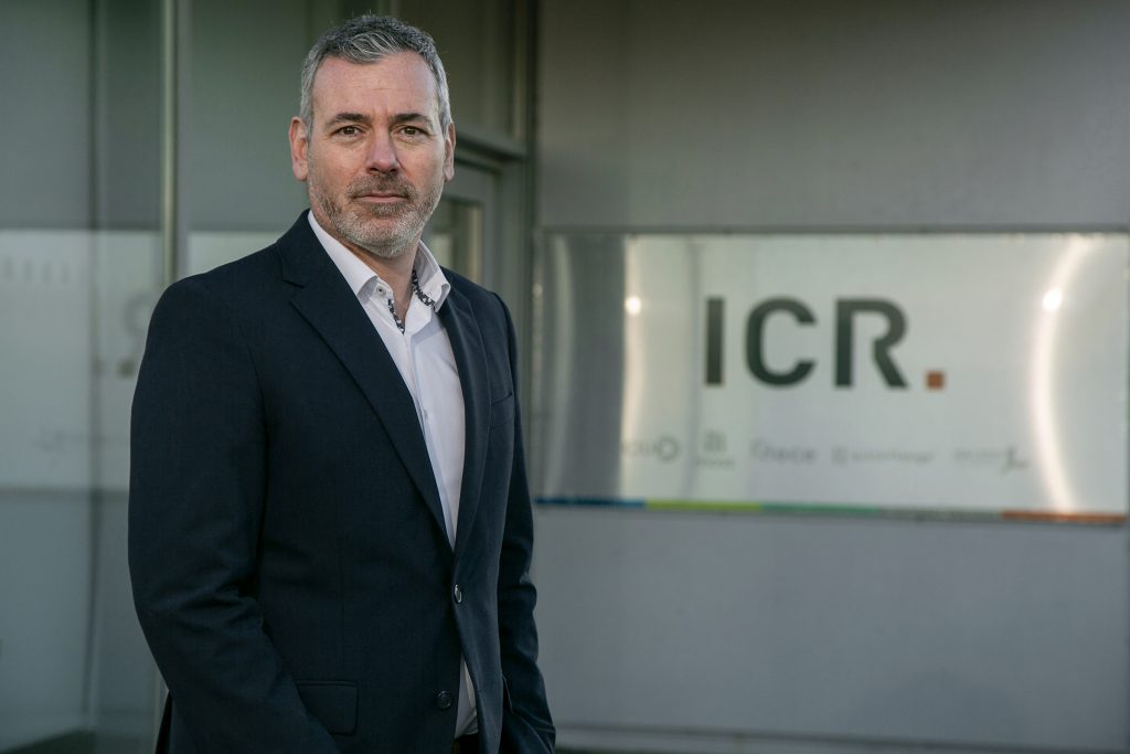
ICR Integrity (ICR), technology-enabled provider of specialist maintenance, inspection, and integrity solutions, recently announced the appointment of Ross McHardy as group director.
McHardy’s appointment will focus on supporting the global growth and diversification of ICR’s repair and maintenance business. He brings a range of experience in senior roles for a number of oil and gas operators including TAQA, EnQuest and latterly at service company EnerMech, where he headed up the Europe and Africa businesses.
His cross-sector knowledge will reinforce ICR’s growth plans including working extensively with partners globally.
Ross McHardy is ICR’s new group director. (Courtesy: ICR)
“I’m delighted to join ICR at a time of growth and diversification for the company — my experience ranges from engineering and integrity, through to projects, asset management, and business leadership, which will bolster the strong diverse team we have at ICR,” McHardy said. “It’s an exciting time for the company and I’m looking forward to further successes in 2023.”
With more than 30 years of experience in providing solutions for a range of industries, ICR offers clients world class repair and integrity solutions providing greater asset uptime and reliability, while saving time and cost compared to traditional repair methods. In 2022 the company increased its global headcount and posted end of year results showing a 12 percent increase in earnings.
“I’m thrilled to welcome Ross to ICR and the senior leadership team,” said CEO Jim Beveridge. “His strong track record and wealth of knowledge will further strengthen our portfolio as we continue to support clients with extensive cross-sector knowledge and multi-skilled teams in power generation, renewables, oil and gas, utilities, and defense industries. Our established repair and maintenance division provides clients with world-class solutions resulting in greater asset uptime and reliability, while saving time and cost compared to traditional methods.
Through our investment in new technology, we are committed to playing our part in energy transition, helping clients reduce their carbon emissions.”
Vestas is presenting a new solution that renders epoxy-based turbine blades as circular, without the need for changing the design or composition of blade material. Combining newly discovered chemical technology developed within the CETEC initiative, and partnerships with Olin and Stena Recycling, the solution can be applied to blades now in operation. Once matured, this will eliminate the need for blade redesign or landfill disposal of epoxy-based blades when they are decommissioned.
Vestas’ blade recycling technology can chemically break down epoxy resin into virgin-grade materials. (Courtesy: Vestas)
“Until now, the wind industry has believed that turbine blade material calls for a new approach to design and manufacture to be either recyclable, or beyond this, circular, at end of life,” said Lisa Ekstrand, vice president and head of sustainability at Vestas. “Going forward, we can now view old epoxy-based blades as a source of raw material. Once this new technology is implemented at scale, legacy blade material currently sitting in landfill, as well as blade material in active windfarms, can be disassembled, and re-used. This signals a new era for the wind industry, and accelerates our journey towards achieving circularit0.”
Turbine blades have previously been challenging to recycle due to the chemical properties of epoxy resin, a resilient substance that was believed to be impossible to break down into re-usable components. This has led to many technology leaders attempting to replace or modify epoxy resin with alternatives that can be more easily treated. Vestas’ solution is enabled by a novel chemical process that can chemically break down epoxy resin into virgin-grade materials. The chemical process was developed in collaboration with Aarhus University, Danish Technological Institute, and Olin the partners of the CETEC project, a coalition of industry and academia established to investigate circular technology for turbine blades.
“The newly discovered chemical process shows that epoxy-based turbine blades, whether in operation or sitting in landfill, can be turned into a source of raw material to potentially build new turbine blades,” said Mie Elholm Birkbak, specialist, Innovation & Concepts at Vestas. “As the chemical process relies on widely available chemicals, it is highly compatible for industrialization and can, therefore, be scaled up quickly. This innovation would not have been possible without the ground-breaking CETEC collaboration between industry and academia enabling our progress until this point.”
Through a newly established value chain, supported by Nordic recycling leader Stena Recycling and global epoxy manufacturer Olin, Vestas will now focus on scaling up the novel chemical disassembly process into a commercial solution. Once mature, the solution will signal the beginning of a circular economy for all existing and future epoxy-based turbine blades.
“As the leading customer solution provider of innovative epoxy systems, Olin is proud to support the anticipated massive expansion in wind energy worldwide,” said Verghese Thomas, vice president, Epoxy Systems and Growth Platforms at Olin. “By utilizing unique technologies, together with our partners, we are ready to recover molecules and convert them into new epoxies that can be re-used in wind-turbine blades. We are excited to bring our expertise and unique asset footprint to this partnership and realize breakthrough sustainable material solutions for existing wind blades and those of the future.”
“In the coming years, thousands of turbines will be decommissioned or repowered, representing a major sustainability challenge but also a valuable source of composite materials,” said Henrik Grand Petersen, MD Stena Recycling Denmark. “As one of Europe’s leading recycling groups with a wide footprint in Europe, we have a central role in the transition to a circular economy. We see this solution as a huge opportunity to take part in making a sustainable solution even more sustainable and circular and are ready to apply our chemical recycling expertise and knowledge to this process.”
For several decades, producing wind-turbine blades manufactured with epoxy-based resin has been standard practice in the wind industry. In the most mature markets for wind energy, the first turbines are reaching the end of their operational life. WindEurope expects about 25,000 tons of blades to reach the end of their operational life annually by 2025.
Once mature, the new solution will provide Vestas with the opportunity to produce new turbine blades made from re-used blade material. In the future, the new solution also signals the possibility to make all epoxy-based composite material a source of raw material for a broader circular economy, potentially encompassing industries beyond wind energy.
WindGuard Certification is now among only 10 companies worldwide that have been approved to issue type certificates for wind turbines according to IECRE OD-501 (“Type and Component Certification Scheme — Wind Turbines”).
In addition to prototype, type, and component certification, the scope of validity includes design evaluation and site suitability conformity statements. The certificate of acceptance confirms that the internationally operating certification body from Varel, Germany, complies with the requirements of ISO/IEC 17065:2012 as well as the rules and procedures of the IECRE system.
WindGuard Certification is one of only 10 companies worldwide to gain approval to issue type certificates. (Courtesy: WindGuard)
The IEC System for Certification to Standards Relating to Equipment for Use in Renewable Energy Applications (IECRE) established by the International Electro-technical Commission aims to facilitate international trade of products and services in the field of renewable energies.
“Certifications under IECRE guarantee our customers not only highest quality and safety standards, but above all the international recognition of their products,” said Jerome Feldhaus, head of type and project certification.
“With our many years of experience in type certification according to IEC 61400-22, we were accredited by the German Accreditation Body (DAkkS) for type certification according to IECRE standards already at the beginning of 2020. The official IECRE recognition was therefore the logical consequence,” said Lars Weigel, managing director of WindGuard Certification.
“We are thus optimally positioned for the future and have further strengthened our international market position. The type certificate according to IECRE OD-501 will be a prerequisite for global marketing of wind turbines in the future. For clients from India and the Netherlands, for example, our IECRE authorization was a decisive criterion for selecting us as their certifier.”