


Any floating structure is at the mercy of battering waves, but when that floating structure is a wind turbine, the need for stabilization becomes paramount. An unstable turbine is unable to generate energy efficiently, which can put a dent in a wind farm’s bottom line.
Leading engineers from the Department of Energy’s National Renewable Energy Laboratory (NREL) were recently awarded a patent for a design that helps protect floating wind turbines from the disrupting nature of ocean waves — a necessary task if floating wind farms are going to become a reality — especially in locations such as the U.S. West Coast.
NREL Principal Engineer Senu Sirnivas, along with colleagues Rick Damiani and Fabian Wendt, has been awarded a patent for his team’s “flexible aquatic substructures” research, which led to the idea of a wind-turbine platform that can survive the choppy waters of the deep ocean.
USFLOWT
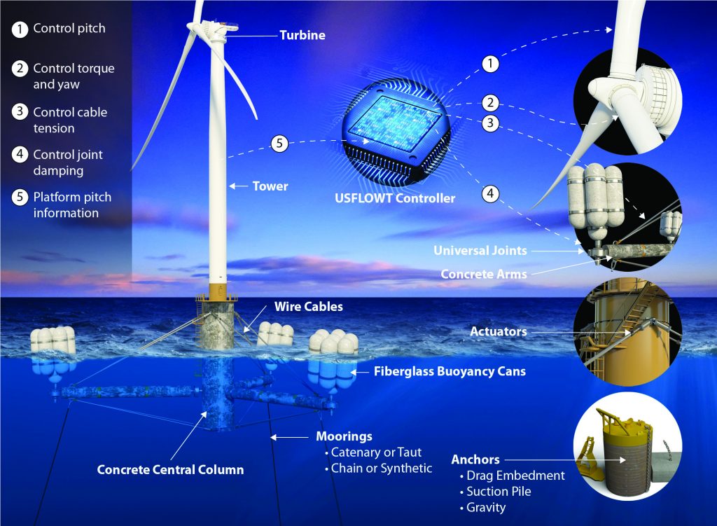
The design, known as the Ultraflexible Smart Floating Offshore Wind Turbine (USFLOWT) can be manufactured, assembled on site, and pre-commissioned, then towed to where it needs to be installed. The platform that hosts the turbine has been dubbed the SpiderFLOAT, since the system’s buoyancy apparatuses spread out from the center like a spider’s legs.
“The No. 1 thing — and this is true for all offshore structures — is you have waves, and waves induce motions, particularly if the structures are floating,” Sirnivas said.
Floating offshore systems usually consist of semi-submersible, TLP, or spar structures, according to Sirnivas. These systems have been adapted from the oil and gas industry, and there’s not a lot of difference for the wind industry other than the structure hosting a turbine.
“These structures are all pretty much rigidly connected, and with waves acting on them, the structure starts to move, the wave-induced loads are then taken up by the entire structure, and you have to design for it,” he said. “Without introducing flexibility, structural members are designed to carry all the loads resulting in a heavier system. In the offshore oil and gas industry, for example, wave-induced loads can be relieved by making the system a little flexible allowing for structural components to be lightweighted.”
Needed Flexibility
To make the structure lightweight, it must allow for some flexibility, which, in turn, allows things to move, according to Sirnivas.
“That’s what the SpiderFLOAT platform — the USFLOWT (SpiderFLOAT with a multi-megawatt turbine) for the ARPA-E project — we have is about,” he said. “It allows some of the wave loads to be mitigated, so it’s not transferred to the entire system. Then, we can lightweight the structural components, and that’s the primary reason, to mitigate the wave loads.”
With a rigid system, waves loads cause the entire structure to pitch back and forth. Active ballasting can be used to maximize the energy captured by actively ballasting/de-ballasting the buoyancy tanks with seawater to keep the system as upright and stable as possible, taking the mean pitch out of the system. It’s still going to pitch back and forth, but from a smaller initial pitch angle in order to capture more energy. The issue with active ballasting is the response time for controls, since pumping seawater in and out of the buoyancy tanks takes considerable adjustment time.
Quicker Reaction
With the SpiderFLOAT system, cables with tensioners are used, which can react a lot faster than active ballasting, where seawater is pumped in and out, according to Sirnivas.
“Our intent is to use these cables by changing the tension to take the mean pitch out and upright the system for improved energy capture,” he said.
Sirnivas, who brings to the table more than 20 years of working with the oil and gas sector, has used his expertise to adapt floating systems used in oil and gas for wind energy.
The oil and gas industry uses one-off traditional semis, spars, and TLPs. One of the main topics to address in wind is serial production, according to Sirnivas.
“You’re not going to build one; you’re going to build 10 or even hundreds of them for a given site,” he said.
Reducing Production Costs
Any type of offshore operation can get very expensive, very quickly, so Sirnivas said anything that can be done onshore, quayside, and near-shore is going to help reduce the overall cost.
Materials is another avenue the project takes advantage of to cut costs.
Whereas many offshore structures are made of steel, the SpiderFLOAT uses mostly concrete, according to Sirnivas.
“Concrete is cheap compared to steel, and concrete is also heavy compared to steel,” he said. “You want all the heavy stuff in the bottom — just like a sailboat with the keel on the bottom — to provide a restoring force for stability. What we have done in our design is similar: keeping the heavy components made of reinforced concrete at the bottom and the lighter buoyancy tanks made of fiberglass above. I call this ‘material use for purpose,’ addressing stability while reducing cost.”
With the SpiderFLOAT system, the legs are connected with universal joints to the central stem on one end and bundled buoyancy tanks on the other. The stem and the legs are made of reinforced concrete. The bundled buoyancy tanks are made of lightweight fiberglass, according to Sirnivas.
“If you look at the construction techniques that we have today, it is easy to pour concrete anywhere,” he said. “With the traditional steel semi, there’s a lot of cutting and welding involved. But with concrete, you can pour them onsite in a single piece. The buoyancy tanks could also be filament wound onsite. The entire system (platform, tower, and turbine) can be assembled and pre-commissioned at port with the onsite manufacturing to minimize the CapEx cost.”
NREL LDRD Funding
The advanced SpiderFLOAT design that was awarded a patent was a Laboratory Directed Research & Development (LDRD) at NREL that spanned more than two years. Sirnivas and his team were to innovate a new cost conscious floater design for wind turbines, which required “out-of-the-box thinking.” The team assembled a list of floater design functional requirements for the U.S., which generated various concepts. Further studies via computer modeling and simulations narrowed it to a single design: the SpiderFLOAT.
Energy I-Corps
The team then continued by participating in the Energy I-Corps program to understand the market and the pain points from the offshore wind-energy industry by conducting more than 70 interviews, which Sirnivas said was tedious, but necessary, for addressing concerns with the design — making it modular and to offer a turn-key solution.
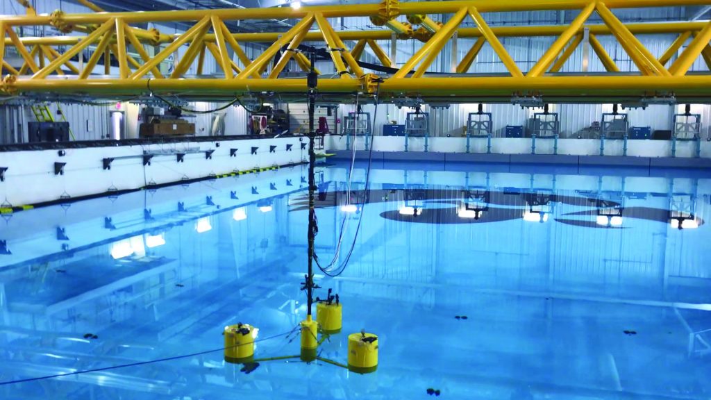
The research continued with additional TCF funding for a scale-model test at the University of Iowa’s wave basin to study the performance of the system, which is a small part, but an important one, to start the de-risking effort, according to Sirnivas.
ARPA-E Atlantis Phase One
Sirnivas said the ARPA-E Atlantis phase one award was a blessing to mature the design using a control co-design (CCD) approach. The team introduced platform actuation to control the platform behavior in-sync with the turbine control to optimize the SpiderFLOAT platform for a 10-MW turbine called the USFLOWT-10. The objective was to achieve an LCOE of 7.5 cents/kWh.
Working together with the American Bureau of Shipping (ABS), Colorado School of Mines, the University of Colorado, and the University of Virginia, the team was able to increase the annual energy production via controls, according to Sirnivas. In addition, gaining the Approval-In-Principle from ABS was a key achievement for the design. The design has continued to evolve from the lessons learned in the wave basin test and the ABS roadmap to address redundancy.
“Instead of having three legs and three mooring lines, we now have six legs and six mooring lines to address a single line failure, improving stability with the buoyancy modules that are more evenly distributed,” he said.
ARPA-E Atlantis Phase Two
The next step is phase two.
“We are one of the fortunate few moving to phase two,” Sirnivas said. “The scope is being defined with the focus on further de-risking the technology, to eventually showcase the advantages and engage the industry.”
Eventually, this research will involve a comprehensive model test that would sidestep what Sirnivas calls a “subscale” design.
“I’m not a big fan of the subscale 20-kW designs in an uncontrolled, open-water environment for many months or even a couple of years, which is in the $10 million-plus range, because in the end, it just goes to the graveyard; nothing happens to it,” he said.
“We’re planning for a bigger-than-usual model test built of the full-scale materials and model-predictive controls for the platform and turbine in the next phase under a controlled environment collecting pertinent information to validate numerical models. This will be used to build a toolset for rapid design and re-engineering given a site and turbine size, and then we’ll approach the industry, particularly the wind-turbine developers, to get them engaged.”
Already, Sirnivas said there is growing interest within the industry about the technology, but he emphasized that the goal is not to rush the results.
“There’s been lots of interest, but our primary responsibility is to de-risk the technology first,” he said. “We also need to make sure that this actually adds value and addresses the industry pain points. We’re first going to prove and show the industry that the technology works, and then outline the value proposition. The thing about the ARPA-E Atlantis program is it’s a control co-code design effort. Traditionally, you would see floating offshore wind-turbine systems are designed to pass information back and forth between the floating platform designer and the turbine manufacturer. The reason being the turbine control algorithm are proprietary and specific to the turbine — they don’t want you to mess with it.”
Independently Designed
Hence, the platform and the turbine are not designed together with the ability to change the control algorithm during the design process (co-design), according to Sirnivas. They’re designed independently and then brought together for a semi-optimal design.
“The objective of ARPA-E Atlantis is to control co-design of the entire system,” he said. “In the USFLOWT, we control the turbine by controlling the torque and blade pitch, and we also control the platform with the actuators changing cable tensions, so it really becomes a control co-design problem. How do you use the controls of the turbine and controls of the platform to minimize the motion and to lightweight the system so we can hit the LCOE target set by ARPA-E Atlantis?”
The meticulous research will push the next phase of the project into four years before a full-scale model of the technology can be tested, but that will show the many efficient ways in which the USFLOWT system can help streamline the burgeoning floating offshore wind sector, according to Sirnivas.
“One of the functional requirements that we had in the very beginning is modularity,” he said. “Accommodating larger, heavier turbines with bigger thrust will not require complete re-engineering of the USFLOWT. So, how do we accommodate? Currently, for the USFLOWT 10 MW, we have six legs, and on each leg, we have three buoyancy tanks. For larger turbines, we extend the legs a little, and add more buoyancy tanks — simple.”
Because of the design’s modularity, it is able to accommodate turbines from 6 MW up to 25 MW, according to Sirnivas.
The interests in the technology is encouraging since there are many offshore areas in the U.S. that could benefit from the USFLOWT design.
Sirnivas said companies with leases off the West Coast of California have shown interest in the design, where it would be beneficial, but other areas could also benefit, including Hawaii, the Gulf of Maine, and the Gulf of Mexico — all deep-water sites with good wind resources.


