


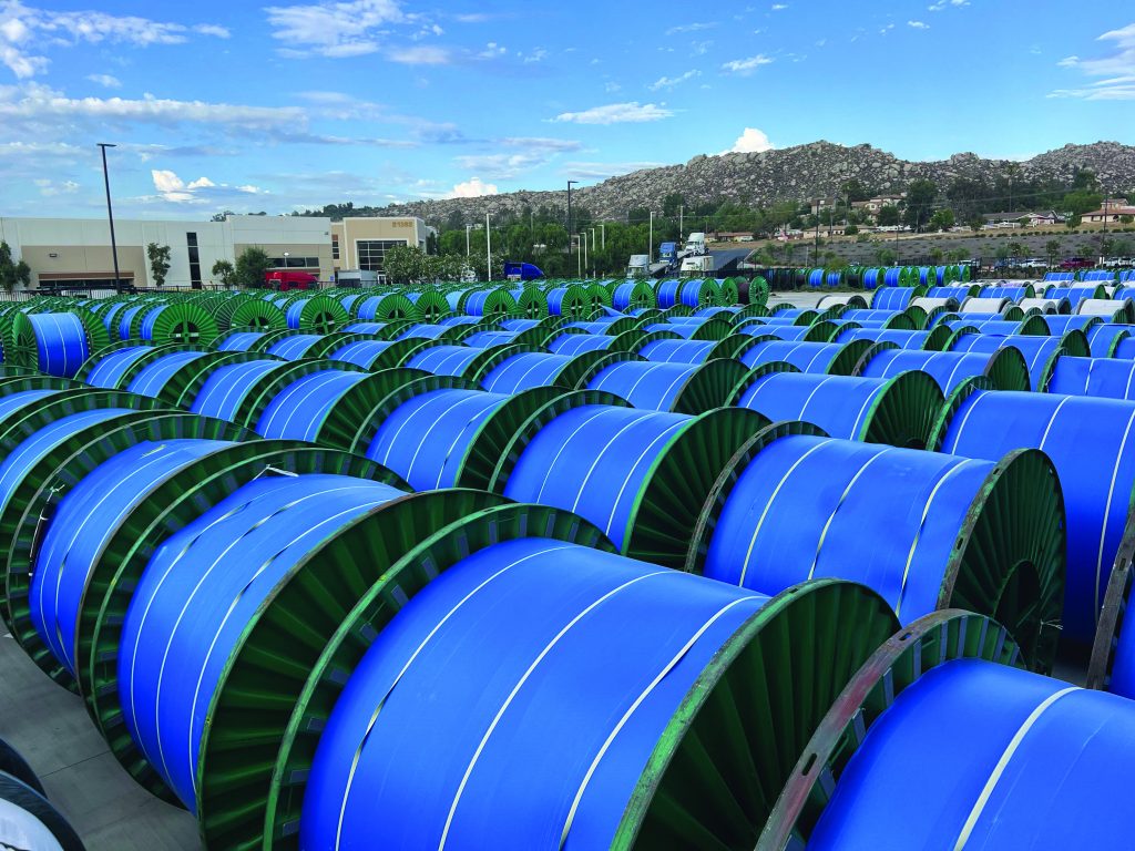
Extruded-dielectric medium voltage (MV) power cables make up the backbone of underground power distribution systems. The construction of MV underground distribution cable provides for a safe, reliable, and economical method of moving electricity where the use of overhead lines is not practical. Transporting power from collector arrays on a wind site is no different. Long-term reliability of wind-site cable systems connected with MV cables relies on quality materials and good installation practices.
MV power cables unlock the potential of wind-collector arrays. Power generation at the individual turbines produces a couple hundred volts of electromotive force, which translate to unacceptable energy losses transporting this voltage across an installation due to the high currents and the resistance losses in the power cables.
It is a widely known principle in physics that transporting electricity over long distances only becomes economical in the kilovolt (kV) range, with current and subsequently losses decreasing as voltage is increased. Transformers within the turbines step up the generation-voltage to distribution-voltage range for transport across the electrical system. However, as this “transport” voltage is increased, the electrical insulation of the underground cable must become larger and more expensive. The design and use of medium-voltage (5 kV-46 kV) cable strive to strike an economical balance between electrical system losses and cost of materials.
Breaking Down the Layers
At the core of MV cables is the conductor, which moves the electricity from point A to B across the system. The conductor is made from either copper or electrical-grade aluminum, with aluminum being the predominant conductor type on wind sites. Although aluminum is not as conductive as copper (approximately 2/3 the conductivity of copper), it is much lighter and less costly.
Since the typical direct burial of MV cables are not restricted on space, large aluminum conductor sizes upwards of 1,250 kcmil and 1,500 kcmil are possible to achieve a higher ampacity. MV underground cable conductors can be solid or stranded. Usually, conductors 1/0 AWG and larger are stranded to maintain flexibility for installation and handling.
Surrounding the conductor is a triple-layer insulation system consisting of an inner semiconductive layer called the conductor shield, the primary insulating layer, and a thin outer semiconducting layer called the insulation shield. The primary function of the insulation system is to keep the electricity within the conductor.
Within the system, the conductor shield provides for a smooth circular interface between the conductor and insulation. The conductor shield also works in tandem with the insulation shield to provide for a uniform electric field within the insulation layer. The insulation layer, made from extruded polymer, is typically made from either cross-linked polyethylene with water-free retardant additives (TR-XLPE), or ethylene propylene diene monomers (EPDM, sometimes referred to as ethylene propylene rubbers or EPR). Both insulation types are not only good electrical insulators, but the process of cross-linking makes them into thermosetting compounds.
Thermosetting compounds, once set, do not melt and re-flow, giving the insulation good thermal stability adequate for the 90°C and 105°C conductor-operating temperature ratings.
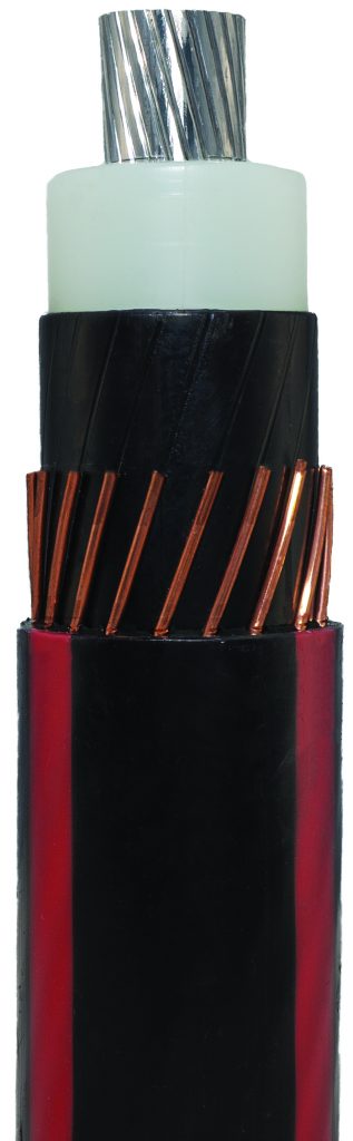
The two remaining layers surrounding the cable core are the metallic shield and jacket. The metallic shield is in intimate contact with the insulation shield and functions as a neutral cable. The metallic shield is made from copper with very little exception and comes in several different configurations depending on application.
The outer jacket is an environmental protection layer and does not carry any voltage rating. There are several different materials that jackets can be made from, with linear low density, medium density, high density, and even cross-linked polyethylene (LLDPE, MDPE, HDPE, and XLPE), being the most common in wind-site applications.
The quality of the insulation system is the most critical part of long-term reliability and long-life performance. The insulation of a properly manufactured cable with quality materials can be considered a homogenous system. The breakdown strength at any point within the system should be similar and even indistinguishable from any other points within the system.
Issues in manufacturing, such as contaminations or voids within the insulation, or damage from installation that compromise the integrity of the insulation shield pose significant risks to performance. In all cases, the exposure of trapped gasses within voids and defect boundaries or the exposure of free air to the high voltage electric field creates localized electric breakdowns that do not immediately cause the entire cable to fail. The phenomenon is known as partial discharge (PD).
When PD occurs within a cable, these discharges erode the surrounding insulation and form carbon structures called electrical trees. These electrical trees grow within the cable, bringing the high-voltage potential from the conductor and the ground plane from the insulation shield closer together over time. Eventually, this distance becomes small enough that the increased electric field strength exceeds the breakdown strength of the bulk insulation, and a full cable failure occurs.
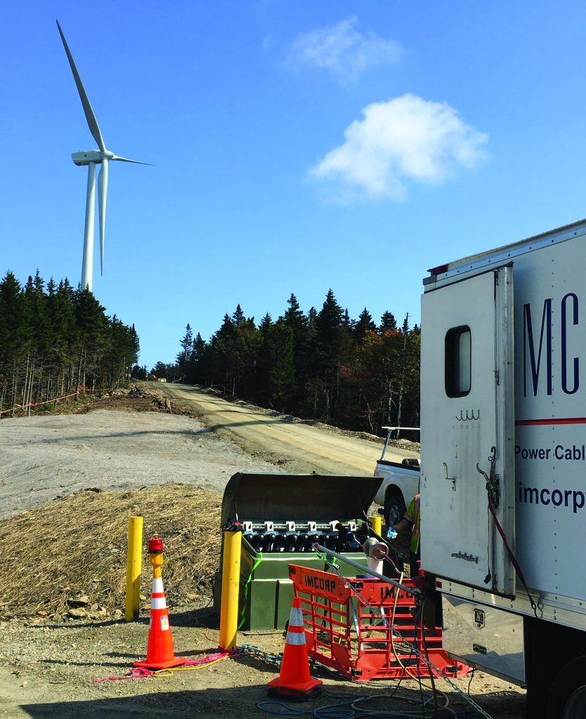
MV Cable Installation
Good installation practices of accessories play as important of a role in long-term cable reliability. When a cable is prepared for a termination or splice, the metallic shield and insulation shield are stripped away from the end of the cable. The termination or splice accessory will “rebuild” these layers, but great care must be taken to ensure the interface between the exposed cable insulation and the inner layer of the accessories are defect-free. Preparation damage, moisture, and trapped air will all result in PD activity similar to that of cable insulation defects and damage, significantly reducing cable life performance.
Using accessory manufacturer instructions, proper tools, and commissioning (ideally with power frequency PD testing similar to the manufacturing requirements), cable preparations with correct dimensions, smooth radial insulation shield cutbacks, proper void filler application, and defect-free interfaces can be assured for expected long-term performance.
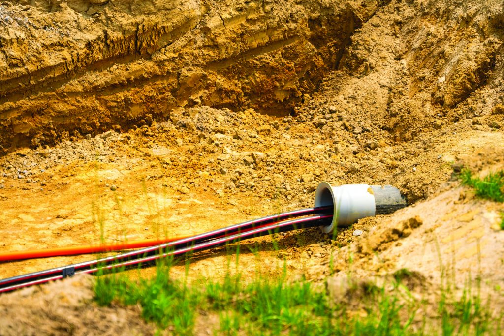
Medium-voltage underground distribution cable allows for the low-loss transport of electric power generated by wind-collector arrays. The high-quality extruded polymer insulation systems are suitable for the direct burial applications ubiquitous throughout the wind industry. Both cable manufacturers and cable installers have their parts to perform in the assurance of long-term cable performance.
Good manufacturing and quality control practices help guarantee that MV power cables are produced defect-free and able to withstand the rated electric-field potential. Cable installers are then responsible for applying the cable accessories in a manner that does not introduce defects at the interfaces between the cable insulation and splices or terminations.


