


With the available and untapped wind resources in the United States, wind power is all but guaranteed to be a boon to its economy for quite some time to come. This represents a great opportunity for manufacturers of the component parts necessary to build and erect them, such as the towers themselves. Three-roll translating geometry style plate rolls are suitable, as well as the “more efficient than popular four-roll machines” for fashioning the conical plate sections used in the construction of wind towers. The following descriptions and illustrations provide a summary of the details and advantages to using the three-roll plate system for wind tower production.
Plate Infeeding and Alignment
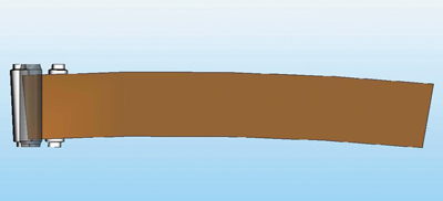
First, the plate is placed on a supporting, motorized rollway and introduced into the three bending rolls (see Fig. 1). The plate is then aligned with the help of two hydraulic side arms. One is positioned on the opposite side of the material infeed, and the other acts as a rollway. Because the plate will become a circular section with a ring shape, the side that will become the small diameter of the cone must possess a smaller amount of curvature.
Therefore, the plate must be aligned at its central axis and fed into the rolls at a slight angle rather than fed parallel to the rolls (Fig. 2). This conical section is where three-roll bending with a variable axis offers an advantage over four-roll bending. The four-roll configuration requires that the material always be presented parallel to the rolls for the entire leading edge to be prebent. If the plate were presented to a four-roll bender at an angle, the corner of the plate would not be prebent. With a three-roll machine with variable axis the material can be presented to the rolls on an angle, rather than parallel to the top roll axis.
First Prebending/Bending
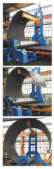
Next, the leading edge of the plate is prebent. The plate is taken through the rolls’ rotation, up to the center of the top and left-side rolls. At the same time the top roll comes down, pressing and bending the plate. The top roll presses the leading edge of the plate, leaving the remaining plate in a horizontal position on the rollaway. To allow the plate to slide, the side rolls must be tilted at the cone angle. The prebending stage is another area in which three-roll bending with variable axis offers an advantage over four-roll bending for wind tower sections. With a three-roll bender, the prebending can be done on the tilted edge of the plate. In contrast, a four-roll machine uses the top and central rolls to pinch the plate, while its side roll lifts the plate to perform the prebending. Because the plate for a wind tower is very long, a bridge crane or exceedingly long “scissor lift” table are needed to lift and reposition the plate.
Once the plate is prebent, it continues its clockwise rotation. The left hydraulic side arm with double articulation supports a medium to large diameter and leads it up to the hydraulic central arm Fig. 3). To get a good bend, the plate should be closed for 80-90 percent of its final diameter during this first cycle. To facilitate and speed up all operations, three-roll benders can be equipped with a control that shows the position of the rolls and the lateral roll’s tilting. The panel helps the operator move the rolls. In addition, it retains memory of the operation so that it can repeat the operation with plates that have the same dimensions. The panel may give other information as well, such as the presence of anomalies or alarms, diagnostics of all electro valves, and monitoring of automatic lubrication.
Second Prebending/Bending
The trailing edge of the plate is prebent in the same manner as the leading edge (Fig. 4). While the plate ends its rotation, the top roll presses on the last section of the plate to prebend it. The lateral rolls are in the same position they were in for the leading edge, just inverted. Next, the plate is closed by rotating it counterclockwise. The two side arms with double articulation and the central arm provide support for the plate.
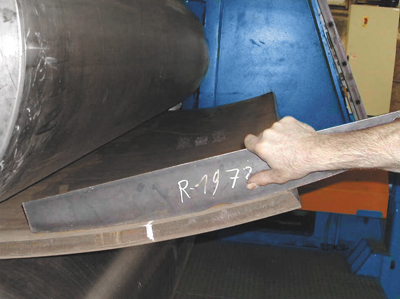
Calibration/Cone Extraction
This phase is important because it helps the internal plate tensions to stabilize, allowing tighter tolerance and eliminating the need to calibrate the plate again in the machine after it has been welded. During calibration the plate is rotated clockwise once again. Altogether the plate is rotated three times from one side to the other. While bending can be performed in just one step, the plate sometimes can have an inconsistent tolerance because of the different mechanical features of the material and the internal tensions caused by strains. Therefore, either the pipe needs to be reinserted into the machine for recalibration, or there will be a long task of welding the two ends. The cone is complete and extracted from the roll bender. Each step shown helps to describe and illustrate the benefits to the translating geometry, three-roll system being used for wind tower production as well as many other common plate rolling applications.
Conclusion
Sertom is widely recognized as the pioneer of many current engineering technologies used to manufacture plate rolls. One of the more popular of these concepts is the translating geometry style plate roll. This style machine allows you to have the prebending capabilities of a four-roll plate roll, as well as the rolling ability of a double pinch three-roll plate roll, with a wider range of capacity and functionality of both. Sertom has placed many of these systems in wind tower production facilities all over the world. Many of these same facilities have abandoned four-roll style machines in order to incorporate these more versatile translating geometry machines in their production facilities. Until recently the focus of Sertom was more of an international one, but with the popularity of wind tower production, as well as other needs for larger plate rolls, this has shifted to a direct focus of the North American market. A newly formed partnership has been created with Carell Corporation to begin Sertom North America operations and support direct from the United States.


