This is a case study of multiple wind turbine towers located in different villages in Alaska where severe arctic weather conditions exist. Initially, a reinforced concrete (RC) mat foundation was utilized to provide vertical and lateral support. Where soil conditions required it, a pile foundation solution was devised utilizing a 30” thick RC mat containing an embedded steel grillage of W18 beams supported by 20”-24” grouted or un-grouted piles. The mixing and casting of concrete in-situ has become the major source of cost and difficulty of construction at these remote Alaskan sites. An all-steel foundation was proposed for faster installation and lower cost, but it was found to impact the natural frequencies of the structural system by significantly softening the foundation system. The tower-foundation support structure thus became near-resonant with the operational frequencies of the wind turbine leading to a likelihood of structural instability or even collapse. A detailed 3D Finite-Element model of the original tower-foundation-pile system with RC foundation was created using SAP2000. Soil springs were included in the model based on soil properties from the geotechnical consultant. The natural frequency from the model was verified against the tower manufacturer’s analytical and the experimental values. Where piles were used, numerous iterations were carried out to eliminate the need for the RC and optimize the design. An optimized design was achieved with enough separation between the natural and operational frequencies to prevent damage to the structural system, eliminating the need for any RC encasement of the steel or grouting of the piles.
Introduction
Wind towers have to sustain continuous vibration-induced forces throughout their operational life. The operating frequency of the three-blade turbine could potentially cause dynamic amplification of these forces, significantly posing a threat to the overall structural integrity. Sufficient separation of the structural system’s natural frequency from the turbine operational frequencies is key to avoiding potentially catastrophic failures. The turbine operating frequency is typically lower than the structural system natural frequency, but could approach it as higher turbine output is obtained. Idealized assumptions of fixity at the base of the tower are un-conservative; a more realistic analysis accounting for foundation flexibility yields lower estimates of the natural frequency for the system. In such cases, soil-foundation-structure interaction needs to be considered.
Structural Description
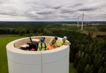
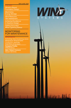
The owner, Alaska Village Electric Cooperative (AVEC), desired to purchase new or used towers to provide wind generated energy in concert with its diesel systems in the Alaska villages of Hooper Bay, Chevak, Gambell, Savoonga, Mekoryuk, Kasigluk, and Toksook Bay, as well as others. The tower models differ in height (23-46m), weight, and wall thickness. Furthermore, the three-bladed turbines vary in weight (7812-7909kg), blade diameter (19-27m), and power output (100-225kW). Towers were from a variety of manufacturers and suppliers. The turbine and tower packages ultimately utilized were supplied by Northern Power Systems of Barre, Vermont. Fig. 1 shows some of the installed towers.
Operational Issues
As the wind turbine blades start to rotate from rest, their circular speed increases, and the induced vibration frequency increases. Depending on its power output capacity, the turbine blades rotate at maximum rotational (circular) speeds that range from 45 to 60 rpm, corresponding to 0.75 to 1.00 Hz. These operational frequencies are very close to the range of natural frequencies of the entire soil-foundation-tower-turbine system.
If more output power is desired, higher rotational speeds have to be accommodated. A poor design decision would involve a maximum rotational speed that is very close to the natural frequency of the structural system, resulting in a high likelihood of resonant amplification causing structural instability. Another poor design would have a rotational speed not very close to yet higher than the natural frequency of the structural system. In such cases the structure would have to endure violent near-resonance vibrations as the operational frequency approaches the natural frequency while speeding up to and down from the maximum speed. This situation would result in very high dynamic forces, which could cause immediate damage to the structure. Even if these dynamic forces do not exceed the structure’s strength capacity, fatigue-induced failures could also be encountered.
A sound design would avoid allowing the operational frequency to approach the vicinity of the natural frequency by a certain safety factor. A safety factor of 15 percent of the natural frequency was recommended by the turbine vendor and adopted by the authors for this project.
Design Objective
In order to develop a sound overall structural system that meets the structural performance requirements of the wind towers, the dynamic interaction of the supporting soil, foundation, and superstructure needs to be considered. Since the tower and turbine are prefabricated and manufactured, once selected for a certain installation location only the foundation can be designed and fine-tuned in accordance with the site soil conditions and desired system frequency.
Depending on the soil conditions, the optimum foundation system needs to be selected (spread footing, deep piles, micro-piles, etc.). Additionally, the foundation must have adequate stiffness in order to maximize the system’s natural frequency within practical limits. A suitably stiff soil-foundation-structure system will allow for higher power output generated by the turbines.
Foundation Design
Based on the geotechnical conditions at the different sites, two types of foundations were selected; large spread foundation, and deep piles. A 5’ deep, 12’x12’ reinforced concrete (RC) spread footing was utilized to provide the system with vertical and lateral support, as well as damping and stiffness. Where soil conditions necessitated it, a pile foundation solution was devised utilizing a 30” thick mat of RC foundation embedded with a steel grillage of W18 beams founded on 20” grouted piles.
After some installations were made, it was determined that the mixing and casting of concrete in-situ is the major source of cost and difficulty of construction. An all-steel foundation was proposed for faster installation and lower cost, but such a foundation system impacted the natural frequency and significantly softened the system. Consequently, the foundation design was driven by the system’s natural frequency. Multiple solutions combining different pile sizes, grouted and un-grouted, and different beam sizes were devised. The optimum design was selected for each location based on the highest practically obtainable natural frequency and cost effectiveness of the design.
Modeling and Analysis
A detailed 3D Finite Element Analysis (FEA) model of the tower-foundation-pile system was created using SAP2000. The tower was modeled using a fine mesh of thin shell elements, while the steel grillage and piles were assigned the appropriate cross-sectional properties. Thick plate elements were utilized to model the RC foundation. In order to capture the soil-foundation-structure interaction, compression-only springs were devised to mimic the soil around the piles. Soil damping properties were conservatively neglected and the turbine mass was lumped at the hub height above the top of the tower. The natural frequency from the model was verified against the tower manufacturer’s analytical and the experimental values.
Discretization of FEA elements into sub-elements is not as straightforward a task as some may believe. Unfavorable discretization can give rise to subsequent numerical difficulties. In vibration analysis, for example, abrupt changes in element size should be avoided, as such changes tend to produce spurious wave reflections and numerical noise [4]. Consequently, a simplified tapered frame element was devised to model the tower instead of the thin-walled shell elements. Negligible deviations of the results from the two modeling techniques were observed. Thus, all design optimization runs utilized the tapered frame element. Fig. 2a, Fig. 2b shows the two different modeling techniques.
The piles were modeled using frame elements, meshed into 1’ segments. The large spread footing, on the other hand, was modeled using a 3D solid element with RC properties (Fig. 3a & Fig. 3b). The solid element was meshed into sub-elements using an intelligent algorithm consistent with the object-based FEA modeling of the SAP2000 program. Fig. 4, Fig. 5, Fig. 6 show the discretization of the piles and footing with the application of the soil springs to the meshed surfaces.
Results
Where piles are used, numerous iterations were carried out to eliminate the need for the RC and optimize the design once a comfort level with the modeling technique was reached. The foundation system design was optimized through a parametric sensitivity-based approach in which the radius of the pile group, grillage beams, and pile sizes were varied to produce comparable alternatives. It was found that the radius of the pile group had the most impact on the system frequency. A favorable radius was selected using a set of typical grillage beam and pile sizes. A series of further variations to the beam/pile sizes and different combinations yielded an optimized foundation design for each site. The optimized designs were achieved with enough separation (15 percent) between the natural and operational frequencies to prevent damage to the structural system. The optimization eliminated the need for any RC encasement to the steel foundation or grouting to the piles, in many cases.
In most cases, an optimized foundation system design for a particular site was also found to be satisfactory for other locations. Thus, a small library of universally applicable standard designs was compiled in an effort to keep the fabrication cost low. Tab. 1 summarizes the final design for two of the tower locations and demonstrates how one optimized design is adequate in two locations with different geotechnical conditions. Fig. 7 shows one of the optimized all-steel tower support foundations.
Conclusions
The foundation system design was controlled by the natural frequency of the soil-foundation-structure system rather than by strength or serviceability considerations. Taking into account the soil-foundation-structure interaction yielded a more realistic estimate of the natural frequency. Had a fixed-base-tower assumption been adopted, significantly under-designed systems would have been incorporated.
References:
1) American Concrete Institute. (2004), ACI 351-04 Foundations for Dynamic Equipment, Farmington Hills, Michigan.
2) J.P. Saylor & Associates, Consultants Ltd. Vestas V27-225kW Specifications and Technical Data, Des Moines, Iowa.
3) Golder Associates, Inc. Geotechnical Reports, Anchorage, Alaska.
4) R.D. Cook, D. S. Malkus and M. E. Plesha. (1989), Concepts and Applications of Finite Element Analysis, John Wiley & Sons, New York, New York, pp. 553-582.


