


This paper presents a general interest construction topic and introduces the unique techniques used to manage and construct a wind turbine electricity farm that was completed in 2006. Although many construction and management issues associated with other types of construction projects are common to these facilities, the design and construction of a wind power project is relatively new and unique. By gathering information through a series of personnel interviews and job site visits, special coverage is given to the contracting system, foundation design and construction, civil construction, tower and turbine erection, and electrical distribution system. Similar to a case study, the paper also presents difficulties encountered during construction and how these challenges were overcome through continued cooperation, communication, and teamwork by the construction professionals delivering the project.
Introduction
Wind power has been in use for centuries, and it has become the leading mechanically-based source of renewable energy (Dodge, 2006). Since the 1970s large interconnected wind-driven turbines and generators have been constructed in “farms” to generate electricity. Recently these farms have become enormous, using large wind turbines, blades, and towers. While some of the design, management, and construction issues associated with other types of construction projects are common to these facilities, large wind farm construction of a magnitude presented in this paper is relatively new and offers unique challenges.
This paper presents the results of a series of interviews and job site visits to a large wind farm under construction. The objective of the paper is to present a general interest topic to construction educators. Additionally, in a case study format suggested by Kardos and Smith (1979), the paper identifies the challenges encountered on the project and how these challenges were overcome.
Project Overview
The Wild Horse project is owned by a public utility company, and it is located on approximately 9,000 acres of shrub-steppe land about 140 miles east of Seattle, Washington. The project is a 229-megawatt capacity wind-powered electrical generating facility with 127 wind turbines. The generators are connected through underground cables to a central electrical substation, which in turn delivers power to the main power grid. To provide access to each tower, over 32 miles of roads were constructed. Civil construction began in September of 2005, and the 380 million dollar project had 100 percent of the generation capacity commissioned by the end of November 2006.
Project Organization
The project was financed and managed by a public utility company, referred to as the owner in this paper. The utility company provided overall project management from an owner’s perspective, and all of the construction work was contracted to private firms. Fig. 1 shows the major contracts between the owner, prime contractors, and major subcontractors.
Owner: The owner contracted with two major organizations, the tower/turbine supplier, and a developer to manage the majority of the construction contracts. The owner also contracted separately to construct portions of the work that were familiar to the owner, such as power line construction. The owner was also responsible for the major planning of the project, including obtaining a State Environmental Policy Act (SEPA) permit. SEPA is a state policy that requires state and local agencies to consider the likely environmental impacts before approving proposed project. Additionally, the owner provided on-site project management, quality control, and documentation during construction of the project.
Tower/Turbine Supplier: The towers and turbines were designed and manufactured by a firm from Denmark. Towers are made of steel and were constructed in three sections totaling 221 feet in height. They were manufactured in Vietnam, and each tower is topped by a 1.8-megawatt nacelle weighing 75 tons. The nacelle houses the turbine, gearbox, transformers, generator, and mechanical and control devices. Each nacelle is driven by three 129-foot long blades that can vary their pitch and are designed to produce power from wind ranging in velocity from about four mph to a cut-out speed of 25 mph. The tower/turbine supplier subcontracted the erection of the towers, nacelles, blades, and initial commissioning, but was responsible for the final commissioning of these items.
Developer: The owner contracted with a “developer” for most of the construction work. The developer acted as a “Construction Manager (CM) at risk,” with a Guaranteed Maximum Price (GMP), GMP-CM type of contract (Mincks and Johnson, 2004). The title of developer originated because the developer initially proposed the wind farm, but later sold the project to the utility company once it was approved for construction. The contract between the owner and developer was negotiated but the developer used lump-sum bid contracts to buy out the remainder of the construction work. The developer has also become the balance-of-plant contractor, securing a contract with the owner to continue to operate and maintain the wind farm.
Project Construction
Roads and Quarries: The 34-foot wide roadbed was designed and constructed to accommodate the width and weight of a 31-foot wide crane and included a 16-foot wide compacted crushed rock surface for vehicle travel. Because of the size of the cranes, the road design also limited vertical grade, vertical curves, and side slope of the travel surface.
To allow erection of the towers, a crane pad was constructed near each tower site using small dozers. The soil was primarily hard fractured basalt that required ripping, but there were also areas of soft compressible silt that required use of geo-textile fabric. Two on-site quarries were centrally located. Portable crushers were used to produce 1 ¼ inch minus and ¾ inch minus basalt aggregate, which was later used both to make concrete at the mobile concrete batch plant, and as a final surfacing for the roads. With the exception of a portion of the concrete sand, all of the aggregates for the project were provided by the on-site quarries.
Foundations: The towers are supported by a cast-in-place, post-tensioned, two-foot thick concrete “ring” ranging from 25 to 32 feet in length. A drill core sample was taken at the center of each foundation location to aid in the preparation of a geotechnical report. Each tower foundation was located in the field using Global Positioning System (GPS) technology. Since drilling and blasting was required for most foundation locations, a drilling crew drilled the rock to a depth of two feet beyond the design depth of the foundations. Drilling proceeded at the rate of two to three foundations per day, followed by blasting of four to five foundations per day. An excavating crew followed the blasting crew using an extended-boom excavator ranging in size from a Caterpillar (CAT) 320 to a CAT 365. Foundation excavation continued at the rate of one and one-half to two foundation holes per day.
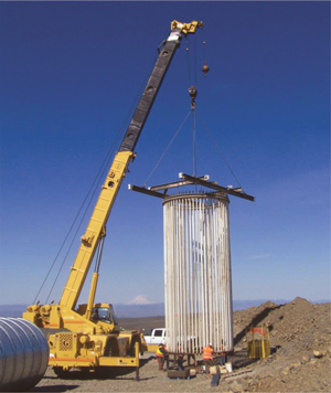
Each tower foundation consists of a post-tensioned high-strength concrete ring formed by two Corrugated Metal Pipe (CMP) forms. The outside CMP is 14 feet in diameter, and the inside CMP is 10 feet in diameter. After excavation, a rough-terrain crane was used to lift and set the outside CMP in the hole. The CMP was then stabilized using concrete gravity blocks and cables and then backfilled on the outside with a 300 psi compressive strength cement-based slurry. Post-tensioning for each concrete foundation “ring” was provided by a “bolt cage” consisting of 120 high-strength bolts. Because the bolts serve as the post-tensioning mechanism, all but the ends of the bolts were encased in a greased sleeve. The cage was assembled in an upright position by a crew who first fitted the tops of the bolts into a steel ring template that matched the bolt pattern in the base of the towers.
The bolt cage was then lifted from the foundation hole by a crane and the bottom steel embedment ring was permanently attached, with a nut on each rod beneath the ring. Next, the inner CMP was lowered into the foundation hole, followed by the bolt cage, as shown in Fig. 2. This assembly was then centered between the two CMPs and cribbed to the proper elevation.
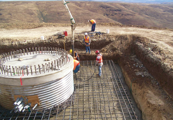
The center of the inside CMP was then backfilled using the foundation excavation spoils. This material served primarily as ballast for the foundation and compaction was not necessary. Next, formwork for a 12-inch thick reinforced concrete floor was constructed on top of the foundation. In a monolithic pour, the concrete foundation ring and tower floor was placed and vibrated, utilizing concrete with a 5,000 psi compressive strength. Approximately 12 of the foundations were located in areas of poor soil and required a square reinforced concrete “collar” four to five feet thick and four feet below grade, as shown in Fig. 3. Tower sections were later bolted to each foundation, with one ring of bolts on the outside and one ring on the inside. Bolts were tensioned in a specified sequence to provide the prestressing force for the concrete foundations and to permanently anchor each tower base section.
Tower, Nacelle, and Blade Erector: The erector was a U.S.-based firm that subcontracted with the tower/turbine supplier to erect the towers, nacelles, and blades, and to transport these large and heavy items from the port to the job site. The erector also prepared, installed, and pre-commissioned the internal components of each nacelle. The erector used two cranes: a 359-ton wheel-mounted crane, and a 550-ton crawler crane. Additional support equipment such as rough terrain forklifts, small wheel-mounted cranes, and maintenance vehicles were also employed. Prior to beginning work, this contractor had to plan and execute a major mobilization effort that involved 43 tractor-trailer loads of equipment.
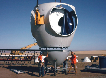
Towers, nacelles, and blades were manufactured overseas and transported by ship to Portland, Oregon, where they were unloaded and moved by truck to the site. Once each nacelle was on site, the blade hub, which contains the blade connection points, controllers and bearings, was connected to the nacelle in a marshalling yard, as shown in Fig. 4.
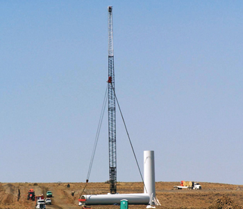
Each tower base section could be set in winds up to 30 mph, while other components could not be set if the wind speed exceeded 22 mph. The upper two sections were initially lifted in a horizontal position. Then, as each section was raised, it was turned upright, using special rigging, and then set on the previous tower section. Tower sections were bolted together from inside the tower. Base and center tower sections were set by the wheel-mounted crane, but the larger crawler crane was used to lift and install the upper tower sections and nacelles. Fig. 5 shows the wheel-mounted crane with the tower base section installed, but installation of the center tower section has been delayed due to high winds.
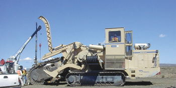
Electrical Distribution: The main electrical substation for the wind farm was constructed at a location central to a majority of the towers. This substation steps up the incoming power (34,500 volts) from each tower to match voltage in the power grid and is connected to the grid through overhead high-voltage transmission lines. Each wind tower is connected through underground wires to the main substation. To reduce heat buildup due to a combination of the high voltage and high ambient temperature of the site in the summer, the underground power distribution system had to be very carefully designed and constructed. The design called for a deep trench and backfill of bedding sand to ensure heat buildup would not damage the cables or reduce their design life. Additionally, in parallel but separate trenches, fiber optic control and monitoring cables were installed between each tower and the main control building located at the entrance to the wind farm. A large chain trenching machine was used to excavate these trenches, as shown in Fig. 6. All underground splice boxes for these cables were located using GPS technology and recorded on a master as-built set of prints and logs.
Case Study
Project Management Challenges: The contract between the owner and the tower/turbine supplier had an unusual force majeure, or act of God, clause. The contract allowed a maximum of 13 days to be considered in the project schedule as a force majeure delay. This type of clause entitles the contractor to a contract time extension, but not monetary compensation (Collier, 2001). If weather-related delays exceeded the 13-day limit, the contract required the owner to reimburse the contractor for additional expenses incurred. The contract was structured in this manner to share the risk of high wind days that could have potentially caused delays during the tower/turbine erection process.
One of the major challenges of this project from an owner’s perspective was obtaining the SEPA permit. Since most of the towers were located on public land, the owner worked with seven different public agencies to ensure compliance with complex environmental regulations. Additionally, the construction of the wind farm in an environmentally sensitive area, and the effects of transporting large equipment and heavy loads, had to be considered. The owner faced some risk challenges due to the relatively tight schedule, which required completing the project before January 1, 2007 in order to receive favorable tax credits. Also, the relatively remote location and large site resulted in resource delivery and allocation challenges.
The tower/turbine supplier was very successful on this project, primarily because of the seasoned personnel this contractor was able to bring to the project. These people were experienced in wind farm construction, having recently completed a similar project. They also were capable of repairing damaged wind turbine blades on site. Due to their diligence, minimal punch list items were discovered during commissioning. They also hired a wind tower erector who was open to suggestions to increase erection efficiency. Teamwork between the developer’s subcontractors appeared to be a major factor in the success of this project. This spirit of cooperation was prevalent throughout the project, primarily as a result of ongoing communication between all parties involved. Although one of the major subcontractors is normally a competitor to the developer, this competitive spirit fostered efficiencies instead of creating tension.
Project Construction Challenges: The project got off to a slow start in the spring of 2006, due to unusually wet weather. Although located in what is essentially a desert, the area had deep winter snow and underground water that created wet soil problems. This caused a delay in the construction of the roads. The mobilized foundation subcontractor pulled off the site for a few weeks, and the tower erector did not mobilize until later than was originally planned. After favorable weather allowed the soils to dry, construction of the roads proceeded in a timely manner. Other subcontractors were then able to make up lost time by properly managing their crews and equipment.
One of the challenges during foundation construction was avoiding over-excavation for each round foundation in the blasted, basalt rock. Since this was accomplished using large excavators with extended booms, the operators were not able to see the bottom of the holes, and any over-excavation resulted in extra slurry backfill around the outside of the CMP forms. Another challenge was the transportation of the 30-foot long CMP foundation forms. Their large size meant that only two CMP forms could be transported over public highways on one truck. This resulted in 127 deliveries. Another issue that became apparent during the construction process was that the embedment ring located on the bottom of each bolt cage needed to be washed clean of any backfill spoils for the post-tensioning process to work properly.
The erection contractor used a Just-In-Time (JIT) delivery system to maximize production and make use of a limited lay-down area. JIT delivery of components allowed for an efficient production schedule; however when a delay at the site occurred it caused a potential backlog of tower sections, either at the site or on the docks, where the contractor was exposed to extensive site storage charges. The specialized rigging, as shown in Fig. 5, allowed the use of only one crane to lift and tilt the tower sections. This also minimized the effects of wind on lifting equipment. Additionally, work started as early in the day as possible to avoid afternoon winds.
Because of the dispersed location along ridges, the towers were installed in groups based on their location. The erection process consisted of first setting the tower base and center sections using the more mobile wheel-mounted crane. Next, the larger crawler crane hoisted the top tower section, followed by the nacelle and then each of the three blades, before moving to another tower. Due to the crawler crane’s slow travel speed, it was moved from one group of towers to the next during the night. The use of modern and relatively new cranes, combined with a maintenance staff that had ready access to crane replacement parts delivered by air, kept downtimes of the two main lift cranes to a minimum.
The nacelles were extremely heavy and had to be transported to the site on special trucks. Nacelle construction was completed in the field, because the nacelle with the hub and its components attached was too heavy to be transported on public highways. By establishing an on-site marshalling yard and developing an efficient assembly operation, this process did not hamper the progress of the project.
One of the major challenges of building the electrical and control cabling distribution system was excavating in the basalt rock. Basalt is hard and homogeneous, and therefore is a difficult type of rock to excavate. The power distribution subcontractor employed two large Vermeer chain trenchers capable of excavating a two-foot wide trench to a depth of 10 feet. Due to the hardness of the basalt, cutting teeth had to be replaced frequently on these machines, sometimes after only 30 minutes of operation. Because of unanticipated trencher breakdowns, the power distribution subcontractor had to mobilize an additional trencher, and had to work overtime to complete this portion of the project in a timely manner.
Conclusion
The Wild Horse wind farm is a unique and large-scale construction project. The uniqueness is the result of the remote, scattered distribution of the towers, specialized foundations, and large heavy-lift items located in a windy environment. This project required the owner, designers, and contractors to work together and to maintain constant communication and a spirit of cooperation to keep the project on schedule. Risk sharing clauses in the contract, a Just-In-Time delivery system for the major components, experienced personnel, and on-site repair capabilities also contributed to the project’s success. As a result, the project was completed on time to take advantage of tax credits available for this type of power production. It was also very successful from a safety standpoint. With the blasting, deep excavation, and heavy lifting there was the potential for a catastrophic accident, yet the only lost time on the project was the result of limited minor injuries. The owner provided on-site management, daily observation, and quality monitoring, and was very satisfied with the completed project.
Acknowledgments
The authors would like to acknowledge the following members of the construction team that provided data, interviews, access, and allowed an insight into their operations during June, July, and August of 2006: Kim Lane and Brian Doughty from Puget Sound Energy: Mike Burtness, Tom Bensel, and Daniel Long from Utility Services LLC; Michelle Berdusis from Vestas; and Dave Hart from Barnhart Crane and Rigging.
References
1) Collier, K. (2001). Construction Contracts (3rd ed.). New Jersey: Prentice Hall
2) Dodge, D.M. (2006, August 31). Illustrated History of Wind Power Development [WWW document]. URL www.telosnet.com/wind.
3) Kardos G., and Smith C.O., Proceedings of ASEE National Conference on Engineering Case Studies, March 1979.
4) Mincks, W. and Johnson, H. (2004). Construction Jobsite Management, Clifton Park, NJ. Thomson.


