


In 2000, the average land-based wind turbine had a hub height of 190 feet, a rotor diameter of 173 feet, and produced 900 kW of electricity. Today, those numbers have skyrocketed, with the average land-based wind turbine now standing 55 percent higher at 295 feet, using a rotor diameter more than two times as large at 410 feet and producing 3,000 kW of electricity — more than three times the amount produced 20 years ago [1]. As the height of wind turbines has grown, so has foundation size, with the average foundation volume doubling in the last 20 years.
As we continue to discover more efficient ways to harness wind’s energy, it’s imperative we continue to develop new solutions to address today’s wind-turbine challenges. One such challenge revolves around wind-turbine foundations. Foundations are critical to wind-energy facility design. Common challenges wind-energy developers face when it comes to wind-turbine foundations include wind-turbine size, site location limitations, and CO2 emissions from the cement used in concrete foundations. Here, we uncover a variety of solutions to mitigate these issues.
Implement an alternative foundation design
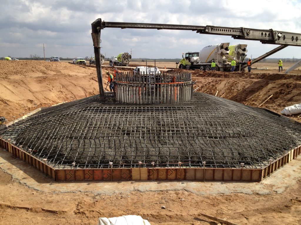
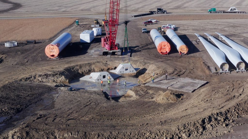
The majority of wind turbines in the U.S. today stand on a spread footing foundation consisting of cast-in-place reinforced concrete. This type of foundation relies on the strength of the concrete, the weight of the turbine, and soil backfill to provide stability and adequately transfer loads to the underlying soil and rock. An example of this can be found in Photo 1.
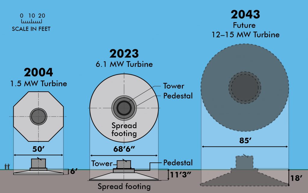
These foundations are already massive structures. As rotor diameters continue to increase and hub heights continue to rise, foundations keep getting larger to support even greater loads. But when will a wind turbine become too large for a traditional gravity-based spread footing foundation? The answer to that question will depend on a number of site-specific factors, including how much concrete can reasonably be supplied to a site at once. (See Figure 1)
When the traditional cast-in-place reinforced-concrete foundation is not an option due to limited concrete supply, alternatives are available. These alternative foundations are based on the principle that concrete volume can be swapped out with higher strength materials and/or by using more efficient geometry.
For example, the floor of a high-rise building could be a flat, cast-in-place reinforced concrete slab. However, today, it is more common for these structures to use concrete waffle slabs or precast post-tensioned concrete due to the shortened installation time, lighter overall structure weight, and the broad industry experience with these methods.
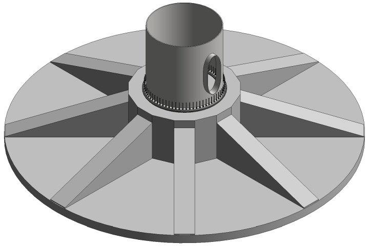
The same concepts can be applied to a wind-turbine foundation. For instance, similar to how waffle slabs are constructed, a ribbed-style foundation (Figure 2) could be used in lieu of a typical foundation with a pedestal and spread footing; it would transfer loads from the wind-turbine tower to a central core, and then through a series of vertical ribs onto a flat bottom slab. This approach is similar to a traditional foundation but requires less concrete.
Using the precast post-tensioned concrete approach, a wind-turbine foundation also can be built using concrete segments that have already been precast off-site, transported to the site, and then post-tensioned. An award-winning example of this approach can be found at the Palmers Creek Wind Farm (shown in Photo 2) in Granite Falls, Minnesota. The Palmers Creek Wind Farm was the first to implement RUTE Foundation Systems’ precast spread footing foundation for one of its wind turbines.
The technology consists of either a cast-in-place or precast reinforced concrete hub connected to multiple precast concrete box girder sections. These sections form a spread footing similar to a typical cast-in-place footing but effectively decrease the amount of concrete needed with the use of post-tensioning steel strands. RUTE received the 2019 Merit Award from the Post-Tensioning Institute (PTI) for the successful installation of the technology.
Another related question is: When will wind turbines become so large that the concentrated loads at the base of the tower become too significant for the materials that connect the tower to the foundation? An innovative approach that supports the greater demand of taller wind-turbine towers is Barr Engineering Co.’s recently U.S.-patented “clamper plate,” as shown in Figure 3. Today’s transportation constraints currently limit the diameter of wind towers, and practical limitations also exist on the diameter and strength of anchor bolts that connect the tower to the foundation.
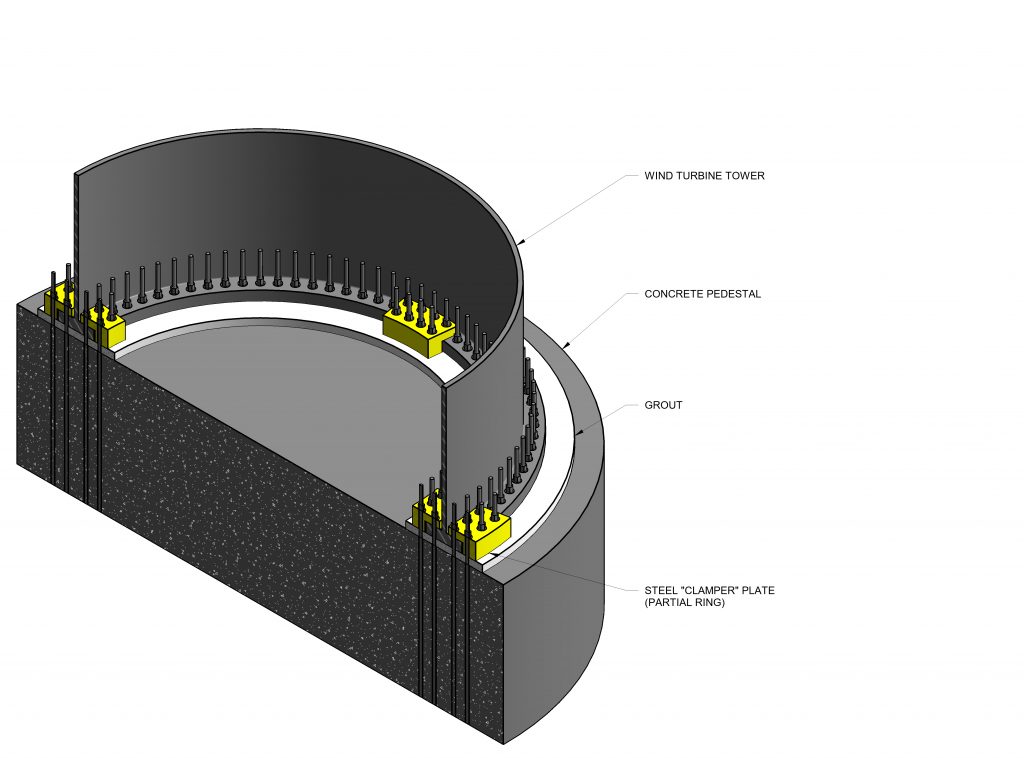
The result is larger turbines are beginning to push the practical limits on the strength of anchor bolts. As wind turbines increase in size, it is essential to improve the method of mounting the wind tower to its foundation without increasing the tower’s diameter, while making sure the diameter and grade of anchor bolts remain practical. The clamper plate attaches to the tower’s flange and allows additional anchor bolts to be installed, supporting the greater demand of taller wind-turbine towers by spreading the load to more anchor bolts.
Repower an existing site or creatively develop a new site
Reliability of wind resources varies across the U.S. Most locations with high-quality wind resources, reasonably economical geotechnical conditions, and close proximity to transmission lines have already been developed. Considering this, what are the best approaches for continued wind facility development?
One approach is to repower older facilities. This can take the form of decommissioning the existing turbines and constructing new wind turbines and foundations in the same general vicinity. This can also take the form of evaluating the existing foundations to assess their ability to support the newer and larger wind turbines. These evaluations typically include two phases: desktop studies and field assessments. In the desktop study, a strength evaluation is completed in accordance with the American Concrete Institute (ACI) 318 Standard, a calculation-based assessment of the as-built characteristics of the foundation.
The field assessment validates the desktop study findings through a variety of activities, including visual observations, performance tests, selective coring of the concrete, and structural health monitoring to collect data on the foundation’s stiffness during turbine operation. Depending on the results of these evaluations, foundations can, at times, be reused without the need for modifications. However, if this is not possible, constructed modifications (e.g., collars, extensions and/or overlays) can be made to strengthen the existing foundations to support larger turbines.
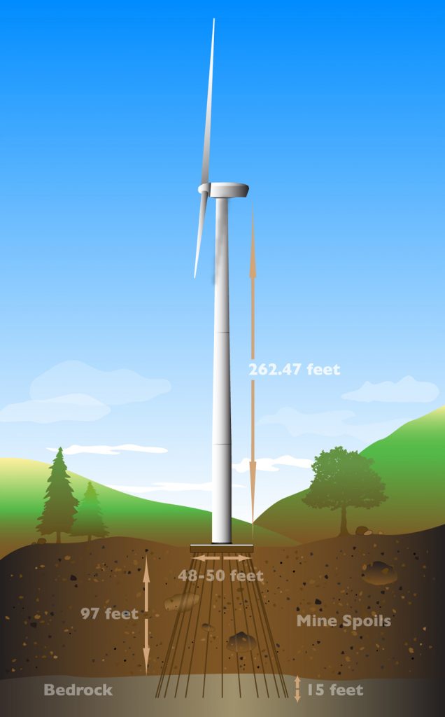
A second approach seeks out sites with high-quality wind resources that have not yet been developed due to geotechnical conditions that make foundation design more challenging. An example of this can be found at the Casselman Wind Power Project in Somerset County, Pennsylvania. Out of 23 wind turbines on the site, eight are on top of a rehabilitated surface mine. Sites that exist on top of mine spoils are highly susceptible to damaging amounts of settlement, making foundation design more complex.
The solution was the design of a micropile-supported reinforced concrete foundation that extended through the mine spoils to the underlying bedrock, as deep as 100 feet below grade, as shown in Figure 4. This innovative foundation design was recognized with the Seven Wonders of Engineering award from the Minnesota Society of Professional Engineers (MSPE).
Reduce concrete use and C02 emissions
The Environmental Protection Agency reported in 2019 that cement plants produced emissions of 67 million metric tons of carbon dioxide equivalents, comprising roughly 10 percent of the industrial sector’s total reported emissions [2]. Cement has been a critical part of the U.S. construction industry for one-and-a-half centuries, but its production results in a significant amount of CO2 emissions. What can be done to reduce concrete consumption?
One direct option is to use an alternative foundation approach that, by design, uses less concrete, as described earlier. This includes ribbed-style foundations and precast post-tensioned concrete segment foundations.
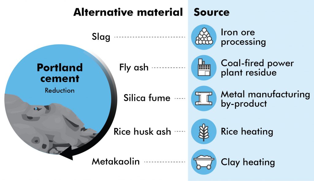
A second option is to use supplementary cementitious materials (SCMs) to reduce or replace the amount of cement used within concrete. A variety of SCMs exist, including fly ash, slag, and silica fume (See Figure 5).
A third potential option — alkali-activated cements (AACs) — were recently investigated by the ACI Committee 242. These materials rely on a reaction of alkali activation to form a cement-paste solid. As the 2022 ACI AACs Report summarizes, “AACs constitute a class of materials that is suitable to use as part of a toolkit of various concrete technologies. Thus, while AACs may not be considered a direct replacement to cement or blended hydraulic cementitious materials for every application, AACs may meet or exceed economic and technical performance requirements in some applications.”
More research is needed before AACs are considered for use in wind-turbine foundations. However, a parallel technology has already been demonstrated in the wind-turbine foundation industry in years past; 20 years ago, when foundations were typically designed for 1.5-MW wind turbines, cement-based grouts were commonly used to transfer loads from the bottom of the tower to the top of the foundation.
However, today, nearly every wind-turbine foundation project uses the stronger, more efficient epoxy-based grouts for the same application.
Conclusion
The development of wind-energy facilities will continue to play a critical role in meeting legislative and societal goals for renewable energy.
However, a wind turbine is only as strong as its base. As wind-turbine technology advances, innovative foundation approaches will be necessary. The good news is a variety of solutions are available for today’s common wind-turbine foundation challenges, with more solutions on the horizon.
References
- “Wind Turbines: the Bigger, the Better,” Office of Energy Efficiency & Renewable Energy, August 16, 2022, www.energy.gov/eere/articles/wind-turbines-bigger-better.
- “U.S. Cement Industry Carbon Intensities (2019),” United States Environmental Protection Agency, October 2021, www.epa.gov/system/files/documents/2021-10/cement-carbon-intensities-fact-sheet.pdf.


