Home March 2010

March 2010

Company Profile: Carolina Gear & Components Ltd.

0

As the wind industry continues its upward trajectory throughout North America, some gear manufacturing companies will be better prepared to service the market’s needs than others due to the nature of their experience and existing capabilities. One such company is Carolina Gear & Components, or CGC, which has spent years manufacturing large components for mining, metal processing, and heavy machine tooling applications, in addition to many others. But the company possesses other advantages as well, according to its managing director, Cosmin Carpinisan.

“CGC used to be a division of Moventas, and I’d worked with them for many years before we had the opportunity to purchase its open-gearing assets in December of 2008, and then all of its wind component manufacturing assets almost exactly a year later,” he says. “We’ve since become their number-one supplier of wind components in North America.”

A mechanical engineer by training, Carpinisan has worked in all aspects of gearing, including design, sales, management, and manufacturing. This wealth of knowledge and hands-on experience is helping establish the company throughout North America, where the bulk of its customers are located, and carrying its reputation into potential new territories such as South America. At present, however, CGC is busy filling the orders it currently has in place, while expanding its facilities and capabilities.

“When we began operations in 2008 we had seven people working here, all of whom came from Moventas,” Carpinisan says, adding that the company is based in Cambridge, Ontario. “Now we’re up to 20 experienced gear manufacturing professionals, and we also have a new addition under construction that will double our facility space to 50,000 square feet. And while we subcontract services such as heat treating, we oversee the entire operation, machining the blanks and handling the finish grinding ourselves. We are dealing with large course-pitch pinions and also gears up to 10 meters for the mining and wind-energy markets, and all strictly according to AGMA, ISO, and DIN standards.”

Carpinisan finds himself on the road quite often these days, traveling to meet with clients to observe their operations and determine how CGC can help them to meet their project goals, and also to help with fixturing and tooling. This close communication provides a deep understanding of how a customer approaches its work, what markets it serves, and what its needs will be in terms of delivery times. In addition, his broad experience in gearbox design and gear manufacturing allows him—along with his colleagues—to make suggestions that can lead to greater production efficiencies. CGC can also help its OEM customers to redesign for increased horsepower or improved load ratings and gear life.

Once the company has moved into its new quarters this summer it will continue exploring new markets in addition to those in which it is currently active, including minerals processing, cement, pulp and paper, environmental/recycling, rubber, sugar processing, telecommunications, and cranes, in addition to those previously listed. It will also keep working to build its reputation in the wind-energy industry as a supplier of quality gearing that takes project deadlines and commitments seriously. CGC also plans to explore additional capabilities and services such as gearbox maintenance, repair, and retrofitting.

“What I’ve learned over the years is that you should listen and gather information first,” Carpinisan says, “and once you have a true understanding of the customer’s needs that’s when you can begin to apply your own experience to the situation. And between all of us here, we have a great many years of combined experience in manufacturing gears of all types, no matter the size, material, or end use.”

For more information:

Call (519) 623-8806, e-mail sales@cgc-group.net, or go to www.cgc-group.net.

Tribological Challenges to the System

The drive for an increase the amount of sustainable energy sources has given rise to increasing interest in the development of wind turbine technology. Although wind turbines are being increasingly installed around the world, several of the components in a wind turbine have challenges related to tribology that can drastically reduce their expected lifetimes.

Introduction

Most modern wind turbines are configured with three composite blades in a horizontal-axis setup, transmitting rotational power to the hub of a center nacelle that is mounted onto a steel tower. The nacelle itself contains a main driveshaft onto which the blades are connected, as well as a gearbox and generator. The rotational power from the blades is thus converted into electrical power inside the nacelle.

Although wind turbines are being increasingly used around the world, wind turbine manufacturers and operators are consistently faced with tribological issues that drastically reduce the lifetimes of gearbox systems and increase costs. The ANSI/AGMA/AWEA 6006-A03 standard [1], which was developed for the specification of wind turbine gearbox design, contains maintenance specifications based upon an expected gearbox failure lifetime of 20 years. However, a number of investigations [2] have demonstrated that repair and/or replacement of gearboxes is required over significantly smaller time intervals than that which is expected. The additional cost of providing unexpected maintenance and/or repair to wind turbine systems significantly affects the cost of wind energy as a whole.

Tribological Components

Gearbox: The gearbox in a wind turbine system generally employs three stages of gear enhancements in order to provide the appropriate speed ratio between the low- and high-speed shafts. The diagram of a typical gearbox configuration is shown in fig. 1. Each stage can be designed in either an epicyclic or parallel arrangement, with one or two intermediate shafts used to transmit power between the low-speed and high-speed shafts. Because of its harsh operational environment, the gearbox as a whole must be developed with a number of design considerations. In particular, the gearboxes must be designed to handle highly varying loads from the low-speed driveshaft due to the transient nature of wind. The gearbox must also contend with braking loads when the overspeed brake is engaged, as the brakes on most wind turbine systems are connected to the high-speed shaft [3]. The gearbox may also be subjected to contamination and large variations in external temperature. Efficiency and noise generation are also significant concerns that are considered in wind turbine gearbox design.

The gears of a wind turbine system are subjected to both rolling and sliding contact under varying load. In order to prevent wear damage to the gear teeth, the gears are typically lubricated using oil. The oil serves to create a thin film between the mating gears, allowing for elastohydrodynamic lubrication (EHL) between the mating surfaces.

Yaw Drive: The yaw system serves to orient the blades in the direction of the wind. This movement is normally only made a few degrees at a time [4]. A commonly used yaw configuration involves a rolling slewing bearing that uses a rack-and-pinion system to allow several motors to control the axial motion. When the correct yaw position is reached, several brake calipers clamp onto a rotor on the yaw drive in order to fix the yaw direction.

Pitch Drive: The base of each wind turbine blade contains an actuator (either hydraulic or electromagnetic) to actively adjust the angle of attack, or pitch, of each blade into the wind. The pitch variation allows the blades to extract an optimal amount of power under varying wind speed conditions, and also protects against gusty wind situations. The pitch bearings are directly exposed to the harsh environment, and must operate under severe loads.

Low-Speed Bearing: Because the main or low-speed shaft is directly coupled to the blades, the low-speed bearing is subject to cyclic stresses that can cause premature failure. The cyclic stress is caused by the varying torque of each blade as it rotates from the highest altitude (where the wind speed is greatest) to the lowest point (where the low altitude and the presence of the tower causes the wind speed to be fairly low).

High-Speed Bearing: Studies have shown that the high-speed bearing is one of the areas of the wind turbine that is most susceptible to failure [4]. A combination of cylindrical roller bearings, four-point contact ball bearings, and/or tapered roller bearings are used to support the applied radial and thrust loads.

Filtration Issues: The gearbox oil is circulated using a distribution system inside the nacelle. In addition to lubricating the mating components, the distribution system also serves to filter contaminants from the oil and regulate the oil temperature. Particle removal efficiency of filters may be limited by pressure losses across the filters, especially during cold starts due to higher oil viscosity.

Contamination Issues
Contamination from both solid particles and water entrainment can be common in wind turbines, and both have detrimental effects on the lubrication of gears and bearings.

Particulate Contamination: Particulate contaminants pose a significant danger if entrained between contacting surfaces. In concentrated sliding contacts (gears) hard particles abrasively wear away material, leading to loss of clearance and loss of power transmission efficiency. Trapped particles in rolling contacts may cause micropitting (dents in the contacting surfaces, as shown in fig. 2), and also the initiation of surface cracks, leading to fatigue spalling. Contaminant particles can either be built in during start-up, be entrained from the environment during operation, or be internally generated. As shown in fig. 3, hard ductile particles typical of gear teeth wear debris are the most damaging for fatigue spalling [5].

Water Contamination: Contamination from water is also a major issue in wind turbine gearbox design. The ANSI standard [3] lists many of the possible detrimental effects of water contamination to the gearbox lubricant. In particular, wind turbine operators have observed that water entrainment in gearboxes can significantly degrade the gearbox lubricant by causing the lubricant to foam or lose its ability to create a sufficient film for EHL contact. Water contamination can also cause the formation of rust on internal components, or react with the additives in the lubricant and diminish their effectiveness. In order to minimize or eliminate the effects of water contamination before the wind turbine is placed into service, it is generally accepted that the manufacturing environment must be clean and dry, and the components must be shipped to the operation site in a manner in which it is sealed from water entrainment. After being placed into service, wind turbines can still be subject to water contamination depending on their operating environment [6].

Additional Notes

A chart of the tribological challenges that are faced by various components in a wind turbine is shown in fig. 4. As the diagram shows, contamination can lead to problems throughout the entire wind turbine system. In addition, there are a number of other tribological issues that are encountered locally.

Conclusion

Wind turbine designs have evolved significantly since their initial growth phase in the early 1980s. As increasingly powerful wind turbines have been designed over the years, more attention has been paid toward providing effective gear and bearing lubrication and increasing gearbox lifetime. Although a great deal of advancements have been made, a number of current and future challenges exist as wind turbines increase in size and their operating conditions become more extreme.

Acknowledgment

From the proceedings of the STLE/ASME International Joint Tribology Conference 2009, courtesy ASME.

References:

1) Musial, W., S. Butterfield, and B. McNiff. Improving wind turbine gearbox reliability. in Proceedings of the European Wind Energy Conference. 2007. Milan, Italy.
2) American Gear Manufacturer’s Association, Standard for design and specification of gearboxes for wind turbines. ANSI/AGMA/AWEA 6006-A03, 2004.
3) Burton, T., et al., Wind Energy Handbook. 2001, New York, NY: John Wiley & Sons, Ltd.
4) Bartz, W.J. Tribological aspects of wind power plants. in Proceedings of the World Tribology Congress III. 2005. Washington, D.C., USA.
5) Errichello, R. and J. Muller, Oil cleanliness in wind turbine gearboxes, in Machinery Lubrication. 2002.
6) Kotzalas, M.N., Needelman, W.M., Lucas, D.R., LaVallee, G.L., Improving wind turbine gearbox life by minimizing oil contamination and using debris resistant bearings.  Proceedings of the AWEA Wind Power Conference, 2008, Houston.
7) Poore, R. and T. Lettenmaier, Alternative Design Study Report: WindPACT Advanced Wind Turbine Drive Train Designs Study, in NREL Report SR-500-33196. 2003, National Renewable Energy Laboratory: Golden, CO.

Remote Site Construction

Despite the location, Vestas is more than equipped to deal with the various challenges associated with remote sites for wind farms, as the following two case studies will attest.

The first, in Arga, Portugal, involved considerations including protecting plants, bats, and wild horses on this beautiful and isolated mountain site where winding roads posed transport challenges for V90–3.0 MW turbines.

The second, in Aapua, Sweden—where temperatures fall as low as -40ºC—made great demands on employees, materials, and planning when Vestas established the most northerly wind power plant in the country.

Case Study #1: Arga, Portugal

How to build a wind power plant with the minimum of disturbance to plants and wildlife was the main challenge facing Vestas and its customer EEVM at the Arga site in northern Portugal. The mountain known as Serra d’Arga overlooks the valley of the river Minho—which forms the border with Spain—to the north and the Atlantic Ocean to the east. The area is home to protected species of plants, birds and bats, semi-wild horses, and until recently the near-extinct Iberian wolf.

But stringent rules on habitat protection did nothing to dampen enthusiasm for the new wind power plant. At an altitude of nearly 800 m the site has excellent wind conditions for the 12 V90–3.0 MW turbines, and local support was strong. Rural incomes are hard to come by, and the once-forested hillsides are now largely bare, supporting only a few grazing animals. As a result, the local municipality has become an enthusiastic shareholder in the project.

Vestas built the Arga plant on a turnkey basis and handed it over to EEVM at the end of June 2006. Since then it has performed well. “There were some delays at the start of the negotiation process,” says EEVM managing director José Miguel Oliveira, “but once the project was under way we had a very good, close, and professional collaboration with Vestas. And we are very pleased with the V90–3.0 MW turbines.”Portugal Project

Planning for Growth

Following recent legislative changes, wind power in Portugal is now expanding rapidly, and the situation in the Minho region reflects this. Before Arga EEVM (Empreendimentos Eólicos do Vale do Minho, S.A.) had already built two small wind power plants of 6 MW and 10 MW, respectively, in the area. The 36 MW Arga project expands this total considerably, but EEVM has even bigger things in mind. The company’s 240 MW Alto Minho wind power plant, which was scheduled for completion in 2009, will span five sites across four municipalities. EEVM is not short of backing since its main shareholder is SIIF Energies, utility giant EdF, and also the Spanish company Endesa through its local company Finerge.

Due to the nature of the Arga site, the planning authorities restricted EEVM to 12 turbines. In situations like this, Vestas project manager João Salinas de Moura points out, it’s especially important to get the most output from each turbine. “We were the only supplier offering a 3-MW turbine,” he says, “so that counted in our favor.”

EEVM had not worked with Vestas before, and the decision to use the V90–3.0 MW turbine—still quite new at the time the project was being planned, in mid-2004—required care, says José Miguel Oliveira. “We spoke to other people who were using the V90 and found that it was very well received in Portugal. The figures from Vestas were also very persuasive. So we decided to go with the V90, and we have not regretted it.” The two companies signed a contract in March 2005.

Site Challenges

The first task, handled by another contractor, was to build 9 km of road: 6 km from the nearest existing road up to the site entrance, and a further 3 km within the site itself. The main entrance is at an altitude of 500 m, and the highest point of the site is at 780 m. Once the roads were completed, in August, Vestas started site work.

The turbine foundations were laid out in a main line of nine and a smaller line of three, and a location for the substation was prepared in the middle of the site. “This is a rocky site, so the foundations were not always easy,” says João Salinas de Moura.

Later in the project, the steep and twisty nature of the local roads were to provide another challenge. “Transporting the 44 m-long blades was a little slower than we had forecast,” João Salinas de Moura admits. “We are talking about two hours to cover 12 km, with lots of tight bends and some narrow bridges. But we managed it all without serious problems.”

Toward the end of the year, winter mountain weather caused some minor delays. Then the real problem started when Vestas discovered a problem with the concrete used for four of the foundations. Work stopped through most of December and right through to March while all the foundations were investigated and a new sub-supplier replaced the defective concrete. “That was a good test for everyone,” says José Miguel Oliveira. “If we hadn’t had such a good relationship with Vestas it could have been a lot more difficult.”

The concrete problem was fixed, and work resumed at such a pace that Vestas was able to complete the project a few weeks ahead of the original schedule. The first turbines were connected in April 2006, and all commissioning was finished in June.

Environmental Protection

Right from the design stage, environmental and planning rules played an important part in the Arga project. The local wildlife and especially vegetation is uniquely adapted to the Atlantic climate, and this threatened ecosystem is scheduled by the European Union as a “Natura 2000” site.

As well as limiting the number of turbines, the planners specified that no part of the turbines should be visible from a nearby monastery that is visited by tourists and pilgrims. “It was quite challenging to make sure that not even the blade tips were visible,” says João Salinas de Moura.

To reduce disturbance to wildlife, the planning authorities specified that the working day should start only an hour after sunrise and finish an hour before sunset. The site roads were also designed with the movements of the local wild horses in mind. “While the construction work was going on, the horses stayed well clear of the site,” says João Salinas de Moura, “but now it’s not unusual to see a group of them in the shade of a turbine tower.”

Building new roads on the mountain has also brought a potential problem with tourists, José Miguel Oliveira says: “Now everyone wants to visit the wind farm, and for the first time at one of our sites we have had to put vehicle barriers on the roads. But we welcome visitors on foot, and we will create an information point and trails for walkers.”

The Arga project showed how it is possible to build an efficient wind power plant on a small site under challenging access conditions, and with the minimum of disturbance to the local environment. It also said a good deal about the working environment between EEVM and Vestas. “EEVM is a very technically competent client with a ‘hands-on’ approach,” says João Salinas de Moura. “When we finished erecting the last turbine at 3:00 a.m., the client’s representatives were still there. EEVM is always asking questions, so we could not possibly mislead them. Throughout the project they were very understanding and cooperative. It was real teamwork.”

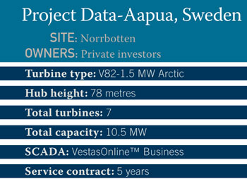
Case Study #2: Aapua, Sweden

In summer the sun shines 24/7 on the little town of Aapua in Norrbotten in Northern Sweden. In autumn, however, when the nights start drawing in, the local population begins to prepare for a dark polar winter where temperatures below -30ºC are not uncommon. Nevertheless, these Arctic conditions did not stop the completion of the most northerly wind power plant in Sweden that, since autumn 2005, has been supplying electricity from its location on Etu Mountain, not far from Aapua.

“We had little time to carry out the work at the site on account of the long, hard winter. But we managed it, thanks to hard work and good collaboration from everyone involved in the project, including our subcontractors,” says Anders Rylin, sales manager at Vestas Sweden.

The Aapua wind farm consists of seven Vestas V82-1.5 MW Arctic turbines. Fitted with special features such as a heated anemometer, wind vane, and nacelle, the turbines have the capacity to generate electricity in the demanding conditions of the long polar night. “Even though winter was particularly hard in Aapua this year, the production figures from the turbines are looking good. In fact, they exceed even our expectations,” says Maria Tevell, one of the 14 private investors who own the wind power plant.

The other owners signed the contract in October 2004 as the winter darkness gently settled over Northern Sweden. Once the contract was signed, it was time to start the preparatory work intended to ensure that it was possible to complete the erection work at the site during the short summer.

Sweden Project

Midnight Sun

One of the first tasks was to lay a road to the site at the top of Etu Mountain (440 metres above sea level) near the town of Aapua. The company Stenger & Ibsen Construction A/S was awarded the contract to establish a 2.7 km access road to the site and lay the foundations for the seven turbines. However, the work had to wait until winter had loosened its icy grip.

“The ground was frozen solid, which meant that it was not drained. Therefore, we could not start work in the area until the end of May. As we had to be finished by the middle of June, we were working to a very tight timetable. Fortunately, the sun was up 24 hours a day, and we made good use of it,” says Johan Stenger, director, with regard to the impressive efforts that resulted in both the road and the seven foundations being ready on time.

As soon as the road and foundations were in place, the turbine components began to stream to the site. The delivery route involved transport by ship from production facilities in Denmark and Great Britain and then a 200 km journey along the roads from Luleå harbour. The erection process went according to plan, and in September 2005 all turbines were in place, connected to the grid and working to repay the owners’ investment in the project.

One of these owners is Maria Tevell, who runs a farm on the Swedish island of Gotland. Wind power is not a new concept for Maria, as since 1994 she has owned a V29 Vestas turbine that generates power on her farm. When the opportunity to invest in a new project presented itself, she was quick to take it.

“Our turbine here on Gotland has run very well ever since it was installed, and when you know a company and are satisfied with its products, you stick with it,” she says. The performance of the new turbines in Aapua during their first few months of operation has certainly not disappointed Maria Tevell or the other owners.

“The past winter was very hard around here,” says Anders Rylin, sales manager. “The temperatures in town dropped to around – 40ºC, but the turbines still returned good results.”

Open Process

Throughout the project, Vestas has worked closely with the Swedish company Siral which was responsible, for example, for selling the shares in the project and for the day-to-day contact with customers during the process.

“Investors are naturally very interested in following the project closely,” according to Thomas Sirland, director. “They want to know that it is on schedule, and they want to be familiar with the product they are investing in. Here in Aapua we have had the chance to follow the construction very closely, which meant that we could provide our customers with the information they wanted. In addition, those investors who wished to do so visited the site while the work was underway to have a firsthand look at the turbines themselves. In my opinion, the investors were very satisfied with the insight they built up as the project progressed, which meant that they could be sure that the work was keeping to the schedule.”

After the completion of the wind farm, investors could still keep a close eye on the turbines. VestasOnline™ Business, the control and monitoring system, makes it possible to use a computer with an Internet connection to keep track of production from the wind power plant as a whole and from individual turbines. In addition, Siral monitors production on behalf of the customers and keeps individual investors up-to-date.

However, the investors are not the only ones to receive returns on the power generated by the wind power plant. Every year the local community receives a cash dividend defined by production. The wind power plant—which was officially opened in March 2006 by Lena Sommestad, the Swedish Minister for the Environment—contributes more than 40 percent of the total electricity consumption of the municipality.

Conclusion: Proven Performance

Wind power plants require substantial investments, and the process can be very complex. To assist in the evaluation and purchasing process Vestas has identified four factors that are critical to wind turbine quality: energy production, operational availability, power quality, and sound level. We spend long months testing and documenting these performance areas for all Vestas turbines. When we are finally satisfied we ask an independent testing organization to verify the results—a practice we refer to as Proven Performance. Contact us to learn more today.

A Direct Drive to Sustainable Wind Energy

0

Early last year the European Wind Energy Association (EWEA) produced one of the most valuable tools for mapping out what are likely to be the dominant commercial trends in the global wind industry over the coming years. In its 156-page report “The Economics of Wind Energy,” EWEA set out to build a holistic financial framework within which the economic factors governing the commercial success of wind energy projects can be identified. Furthermore, the research ranks individual economic factors in terms of their marginal impact on the overall cost of producing wind energy over the lifetime of any wind project. In doing so the EWEA analysis spells out not only the most important considerations that wind project developers face and the factors most strongly impacting their commercial decisions, but also the medium- to long-term consequences for innovation and technology development within the industry’s entire supply chain.

Foremost on the EWEA list is the total number of full load hours (FLHs) accumulated by installed wind turbines over the lifetime of a project. The importance of this is revealed by the fact that a 90-percent increase in FLHs results in an approximate halving of energy production costs. Then there is the cost of financing. Advocates of replacing the UK’s current market driven return-on-capital system with a fixed feed-in tariff—with the aim of increasing the financial attractiveness of UK wind energy investment—should take a well-deserved bow, and once again point to the far greater rate of renewable energy deployment experienced in Spain and Germany.

fig. 1

At its most basic the FLH issue boils down to the simple fact that the more hours a turbine runs at its maximum rated power level, the more electricity it will produce each year and the lower the unit cost of production becomes. Unlike thermal power, the marginal cost of energy production for installed wind turbines is zero. Borrowing a phrase from real estate agents, the crucial thing about achieving maximum load hours is location, location, location. On average, onshore sites achieve around 2,000-2,500 FLHs a year, compared with an average 4,000 FLHs for offshore sites. Such a divergence in output means deployment of turbines will be given priority to offshore locations. In fact, EWEA forecasts that the percentage of turbine investment in offshore sites will rise from 25 percent in 2015 to about 60 percent by 2030.

Now consider the economic benefits of installing larger rated turbines. For example, the average cost of electricity production at a coastal site has decreased from approximately €0.09/kWh for a 95kW rated turbine to approximately €0.05/kWh for a 2 MW turbine. Put simply, the larger the rating of your electricity generator the proportionally smaller your infrastructure costs become per installed MW. Look no further than the release by REpower and Multibrid of 5 MW turbines or Clipper Wind’s ambitious development of a 10 MW turbine to see the trend set in motion by this economic reality.

Inevitably the success (or failure) of producing the most cost-effective wind turbines for the offshore industry will have a direct impact on the future shape of the wind industry as a whole. As wind power developers seek higher rates of return from their offshore locations by deploying ever-higher rated turbines, the one factor that will scuttle this aspiration is reliability. Reliability in the offshore market is of critical importance to developers as the time to repair turbines can be greatly extended by harsh weather conditions that restrict accessibility for maintenance work, thereby increasing downtime in periods of strong winds typically associated with the best power generation conditions.

Overall reliability of wind turbines comes from a huge range of factors such as operations and maintenance procedures, monitoring equipment, use of new materials, better control systems and experience (the learning rate within the industry currently sees between a 9-17 percent reduction in cost for every doubling of installed capacity). These numerous factors are driving a multitude of innovations and to date extraordinary progress is being made in many areas of wind turbine components.

But the issue that continues to afflict the industry is the reliability of the drive train. Put simply, one of the major challenges in producing wind energy is taking power captured by slow spinning blades (rotating at between 15 -24 rpm) and turning it into usable electricity using a high-speed generators (rotating at between 1,500 and 3,000 rpm).

Mechanical Approach

To date, the industry has relied on a traditional mechanical engineering approach to this problem—namely the use of gearboxes. Reliability issues with wind turbine gearboxes is common knowledge (a quick look at the provisions on the balance sheets of some of the major gearbox manufacturers highlights this) and stems from the extreme engineering challenges that gearbox technology faces in wind applications. The most common approach is to use a three-stage gearbox with a high gear ratio (i.e. 97:1). Operating large complex gearboxes in wind turbines is causing a number of difficulties for both developers and turbine manufacturers and it is very difficult to see from where significant improvements in gearbox technology can come. The issues surrounding gear wearing (leading to failure and downtime), handling of multi-directional forces (turbine blades tend to flex in multiple directions as they pass the wind shadow of the turbine tower), need for replacement of large quantities of oil (an increasing concern in environmentally sensitive areas such as offshore), and component weight (the Winergy three-stage gearbox used in REpower’s 5M machine weighs 63 tonnes) are hitting very serious limitations and any real improvements are hard to envisage in what is an old and matured technology. These problems are increasing as the industry moves towards larger more powerful turbines and already there has been a shift away from traditional high-speed copper generators.

Interim Measure

Looking more closely at some of the latest turbine designs to come to market, wind farm developers will see a common trend quietly emerging that speaks volumes about concerns that manufacturers have about the reliability of gearboxes and the overall drive train. After all, why fix something that isn’t broken? And that trend has been to replace traditional high-speed copper generators in favor of lower-speed permanent magnet (PM) generators. The financial edge achieved by employing slow-turning PM generators is that it enables the use of simpler gearboxes which provide more reliability, require less down time and generate more FLHs. One example of this trend is the latest 3 MW machine from Vestas.

Named the V112 and succeeding the 3 MW V90, the latest Vestas machine has a PM generator in place of the high-speed copper machine used in its (same rated) predecessor. Then there is most recent 3 MW machine from WinWind which also uses a PM generator. Or the 5 MW Multibrid machine produced exclusively for offshore deployment, also powered by a PM generator. Or Clipper Wind’s evolving “Quantum” drive, powered by no less than 4 PM generators. Although the list continues to grow, PM generators offer a limited solution and cannot be considered as a long-term solution to reliability due to problems surrounding the weight of the machines, their degrading performance, difficulty in handling sizable permanent magnets and of course the increasingly-restricted supply of rare earth materials from China.

Electrical Approach

Luckily there is another more sophisticated approach to the problem of slow spinning blades and high-speed generators, and that is to take an electrical engineering approach to the problem as opposed to the mechanical engineers’ dependence on clunky, unreliable gearboxes. The outcome here is the use of multi-pole “direct” drive generators. Put simply, these generators are able to produce electricity while spinning at the same low speed of the wind turbine blades. And this is achieved by adding into the generator more electrical “poles,” or copper coils. These extra poles enable the machine to generate torque at low speeds and efficiently convert the slow movement of the turbine blades into useable electricity. This eliminates the need for a gearbox and ultimately creates a far simpler (in mechanical terms) design with far fewer parts moving at far slower speeds.

This approach has already been put to good use by German turbine manufacturer Enercon, which has produced the most reliable, but not necessarily the cheapest, direct-drive wind turbines on the market. In view of the economic impact of FLHs, the financial aspects of “cheap” requires further consideration. Further to Enercon’s success, the attraction of the direct-drive approach recently received another significant endorsement when GE acquired the Norwegian direct drive turbine manufacturer Scanwind as part of its well-publicized bid to improve its presence in the offshore market.

fig. 2

So it is safe to say that wind turbines powered by direct-drive generators with no gearbox requirements are going to play a major role in improving overall turbine reliability and financial return for wind developers. But even within this technology, there is a limitation.

Owing to the additional copper poles used to generate the torque at low speeds, direct-drive generators are very heavy.

Furthermore, the weight of direct-drive generators increases rapidly with increases in electrical rating. For example the direct-drive generator used in Enercon’s 6 MW turbine weighs in the region of 450 tonnes and the company has since focused on producing 2 MW and 3 MW turbines for the onshore industry. At 450 tonnes, problems rapidly develop with transportation and installation, particularly with the availability of lifting ships capable of deploying such weights in an offshore environment. Day rates for such specialized offshore vessels are substantial and can lead to dramatic increases in offshore wind project installation costs.

Superconductors

The wind industry has come up against some very harsh technical limitations where gains on one front (reliability) are offset by losses on another (restriction on size). In situations like these, real breakthroughs in technology are needed, and in the case of wind industry generators this may come from a set of materials called superconductors.

At their simplest level, superconductors conduct electricity with no electrical resistance and, as well as being 100-percent efficient (no heat losses from resistance to electron flow), they can carry more than one hundred times the amount of electricity than copper wires. Or put another way, you need only one hundredth the material for any given electrical application. As a result, they can be used to replace the bulky copper poles found in direct-drive generators to bring about substantial weight reductions that produce a radically different financial equation for direct-drive turbines. In doing this, manufacturers can produce direct-drive generators (high reliability) that are approximately one sixth the weight of copper-based machines (enabling the use of high rated equipment).

fig. 3
Encouraging work has already been carried out producing a new class of generators that can break through the restrictions of traditional technology. By next February German utility E.On will become the first power producer to put a superconductor-based generator into commercial use. Built by Converteam SAS using superconductor technology from AIM-quoted Zenergy Power, the generator is expected to herald the development of an important new technology sector for power generation. In addition to the E.On project, Converteam and Zenergy Power are also building a 10 MW class direct-drive superconductor generator that will weigh 80 tonnes compared to the 450-tonne weight of a copper-based 6 MW machine.

If successful, the use of superconductors in generators is thought to have the potential to reduce offshore wind power costs by 25 percent simply by the reducing the amount of steel in the turbine tower and the amount of concrete poured into the foundations of the unit. Cheaper transportation and shipping costs will also play a major factor in cutting wind farm development costs. Significantly, given the extensive research already carried out and the emergence of working demonstration models, it may just be a matter of years before the financially-attractive role played by superconducting technology in producing large-scale offshore wind power becomes obvious to everyone.

New Systems for Sleeker Turbine Production

0

Not since the revolution in aerospace manufacturing has the need for lean solutions that combine composite fabrication and large-part machining been so critical to an industry’s advancement as it is now for wind energy. Like aerospace, the solutions require breakthrough automation technologies that enable lean, repeatable mass production of large composite and metal components. Fortunately, the foundation for a rapid evolution of manufacturing technology for wind power components was created by the experience of the aerospace industry, and it is already producing results. Aerospace providers have developed automation solutions for parts from blade tip to output shaft, including Rapid Material Placement and quick-cure mold systems for blades that combine to reduce composite lay-up, infusion, and curing time by 50 percent. And an array of new multitasking machine tools for super-sized metal components can, in many cases, produce completed parts in a single setup, minimizing dangerous part handling and improving part accuracy.

Massive Manufacturing

The imperatives driving wind turbine engineering and manufacturing are in many ways analogous to those of aerospace. The parts are massive, ever lighter, stronger, engineered for safety and reliability, and made with advanced metals and composites. The scale of the parts is generally increasing, while a drive for weight reduction is always pushing those parts to their engineering limits.

On the manufacturing side there’s a need to automate with improved process control, repeatability, and process capability, while working with evolving composites and large metal components. Aerospace and other sectors of the energy industry have met this challenge with game-changing manufacturing technologies in composites and metalworking. In composites, automated tape layers and fiber-placement systems revolutionized the manufacture of large aerostructures. In metalworking, purpose-designed aerospace machine tools with multiple spindles addressed the need to produce multiple large parts in a single setup, working with aluminum or the toughest titanium.

The critical mass to support similar developments for the wind-power components has been building, and new purpose-designed technology was rolled out at WINDPOWER 2009 in Chicago. New composite technologies are tailored to the cost requirements of the wind industry—which are quite different from aerospace—and flexible enough for use with glass, the dominant material, and carbon fiber. One of the most innovative is a systematized approach consisting of a Rapid Material Placement System (RMPS), combined with a patent-pending quick-cure molding system. Together they can reduce lay-up, infusion, and curing time by 50 percent.

Fig. 1

For metal components, the principal thrust in wind power is large-part multitasking capability—the ability to complete more metalcutting operations on one machine, or completely finish a raw part on one machine. These manufacturing technologies bring distinct advantages to wind power components, chiefly lower cost, higher performance, and lower warranty/ownership costs due to lighter, stronger components produced to tighter tolerances, and with the repeatability only automation can deliver.

Automated Fabrication

Rapid Material Placement technology brings an integrated approach to what has largely been a manual or piecemeal-automated process. A system like this is capable of spraying in-mold coatings, dispensing/lay-up of glass and carbon fiber materials, and dispensing/application of adhesive. It brings 3 m/sec (10 ft/sec) lay-up speed to placement of materials in blade skin, spar cap, and sheer web molds, with laser- and vision-based wrinkle detection in cross or longitudinal directions. Depending on the laminate schedule, this type of system can reduce lay-up time 85 percent on a 45-meter blade.

Fig. 2

Programmed off line, the CNC-controlled machine uses a gantry system with multi-axis end effectors capable of manipulating spray heads and adhesive applicators, as well as tooling for spooling and placing materials. Two such systems adjacent to one another can each produce a 45-meter blade-shell half in less than two hours, with half the manual labor. The gantry system rides on rails that are flush with the floor, and carries bulk supply systems for gel-coat and adhesive.

After application of gel-coat with spray-head tooling, a ply-generator with a 10-roll magazine of material cuts and dispenses plies to a lay-up end effector on the gantry. The lay-up end effector spools up the material supplied by the stationary ply generator. As the fabric is paid out onto the mold, a pair of articulating, powered brushes smoothes it to the tool surface. The lay-up system is mechanically repeatable to ±2 mm, with application tolerance of ±5 mm.

Off-line programming software supplied with the system creates the CNC code from imported CAD data. The same software can program a related five-axis machining system for root drilling/milling/sawing.

Fig. 3

New quick-cure mold technology uses specialized tooling built to the customer’s specs. The molds are produced using the customer’s CAD data. The system yields a finished blade to spec with each cycle. It can be infused with resin in an hour, followed by a two-hour cure, about half the normal time. Like the lay-up system, the infusion/curing system includes process control metrics for resin metering, temperatures, blocked channels, etc., with alarm limits. Other new blade fabrication technologies include a five-axis machining system for root drilling/milling/sawing.

Multitasking Metal Parts

Many of the main metal components of wind turbines start out as castings or forgings that can require hundreds of hours of precision machining. Part accuracies are as high, or higher, than those of aerospace parts. Machining challenges include tight tolerances, capacity/throughput, complex geometries, inline bore precision, parallelism between bores, bore concentricity, and precision mating surfaces.

Meeting these challenges on large parts is complicated by part weight and size. Great risk and time are involved when parts weighing up to 80,000 pounds are transferred from one machine to another to produce different features on different surfaces. Such transfers often degrade overall part accuracy, too, as tiny setup errors stack up each time the part is refixtured. Reducing part transfers, and the attendant increased WIP, is the essence of lean manufacturing. It’s all about one-stop processing, and it’s accomplished with multitasking machine tools: machines the integrate normally dissimilar operations, such as milling, turning, drilling, tapping, perimeter scalloping, boring, hobbing, and grinding.

Fig. 4

Four primary metal-cutting machines for massive wind turbine components—horizontal boring mills, vertical turning centers, horizontal or universal machining centers, and horizontal turning centers—are increasing their multitasking capabilities to meet the needs of the wind industry. Key components produced on these machines include rotors/shafts, gear case assemblies, planetary carriers, hubs, rotor bearings, couplings, pinions, cylinder brackets, yaw beams, and rotary crowns.

New developments in horizontal turning machines—for rotor shafts, pinions, and similar shaft-style parts—combine a wide array of unusual capabilities for finishing a large part in one setup. These horizontal turning centers (HTCs) perform operations unheard of on a typical HTC: deep-hole drilling, serrating, grinding, hard turning, notch milling, and hobbing, as well as cut-to-length and centering, rough, and finish turning. European wind industry leaders are already using these machines to produce parts up to 1500 mm diameter and 2800 mm long.

Horizontal boring mills (HBMs), used to process gear case assemblies, planetary carriers and hubs, are increasing their one-stop processing capabilities with contouring heads and programmable boring bars, which reduce the number of tools (and tool changes/time/cost) need to complete a part. One tool can bore multiple diameters and produce complex part geometries. A contouring head combined with a programmable boring bar can perform nine to 10 different operations (atypical for a boring mill) on a part, including threading, grooving, turning, contouring, taper turning and others, internally and externally. Right-angle heads and precision rotary tables add capabilities for five-sided part processing in a single setup.

Vertical turning centers (VTCs) for production of bearing rings and planetaries normally apply a stationary tool on the end of a movable ram, but automatically interchangeable powered heads allow VTCs to add capabilities for drilling, milling, tapping, and similar operations with live tooling, all in one setup. The addition of a full-contouring 360,000-position C-axis table now enables drilling or mill turning of features anywhere on the workpiece. Turret heads provide excellent productivity on parts that don’t require a lot of reach into the part. Vertical turning centers handle parts up to 4700 mm (185 in) diameter or larger.

Fig. 5

The Universal Machining Center (UMC) is what its name implies: a machine that can approach a part from a horizontal or vertical orientation. Designed for large, complex-geometry parts, the UMC allows five-axis/five-side machining, with automatically interchangeable heads for faster processing and reduced work-in-process. With a spindle ram mounted on a crossrail, this machine can have a rail or moving-bed design. A rail design allows the machine to have multiple work zones under the spindle, so operators can load and unload parts while the machine continues operations in other work zones. Another new machining concept places a torque table in the work zone of a UMC to enable the machine to do turning work with fixed tooling. This effectively adds vertical turning capabilities to a machining center.

Horizontal machining centers are a mainstay of prismatic parts manufacturing, and the machines are growing in size, speed and multitasking capability to meet needs in wind energy manufacturing. Twin-pallet machines for wind parts typically have a table size of 1250 x 1600 mm and accept parts weighing up to 7000 kg (15,400 pounds). Twin pallets and quick work change ensure high production rates, while robust, cast-iron construction and oversized ballscrews provide muscle and traverse speed to process large parts in volume.

A Strong Start

Dowding Industries entered wind energy manufacturing last year, following a methodical plan. It focused on uptime and commonality of controls. A family-owned company, in 2006 Dowding began looking for opportunities to grow while avoiding the region’s industrial downturn. Already a manufacturer of fabricated and machined components for a wide range of industries, it was particularly attracted to the potential for wind turbines and alternative energy, according to Jeff Metts, president. “We saw an opportunity to be part of the ‘new energy’ solution,” he says.

To help in understanding the business potential before investing, Dowding enlisted the assistance its primary supplier of machining systems, a company with an excellent track record at Dowding. “Our critical success factors were uptime and common controls,” Metts says. “Solid OEM service plays a big role in uptime for large machines, and homogenous controls allow us to be ambidextrous within our machine capability and simplify our training.”


Fig. 6

The machinery supplier provided extensive application and time studies, based on wind generator part prints provided by Dowding. “The detail and thoroughness of the reports were overwhelming,” he says. “The studies included machine recommendations, fixturing, set-ups, tooling, cycle times, and earnings per hour. We addressed the risks and unknowns, giving us the comfort level as newcomers to large-part machining to make such a major commitment.”

Dowding ultimately purchased three massive machining systems in 2008, and Governor Jennifer Granholm helped dedicate the new 35,000 square-foot facility for production of turbine components and large, critical parts for other big-machine makers. “All these machines are built right here,” Metts says. “That is another important factor for us. We were convinced our success would be found here in the United States.”

The recent stimulus-driven, three-year extension of the production tax credit for renewable energy investment should help ensure Dowding’s success, as well as that of other manufacturing entrepreneurs.

Optical Ice Sensors for Wind Turbine Nacelles

Just as airplanes, refrigerators, radio broadcast towers, vehicular overpasses, and bridges are all succeptible to ice formation, so are wind turbines that are sited in cold-weather locations. And not only do O&M professionals monitoring remote turbines need to be aware of the onset of ice formation, they also need to know how fast it’s accumulating.

The most common type of ice detector on the market today involves a vibrating tuning fork sensor, whose design dates from the 1980s. It is essentially an electromechanical technology that operates as a vibrating rod. In the case of an airplane, the rod is mounted so as to be exposed to the passing airstream. If there’s no ice on the vibrating rod, it resonates at its natural frequency. But if it has a coating of ice the additional weight slows down the vibrations, which changes the frequency. The frequency change is detected, then calibrated into ice weight, and ice thickness, and subsequently used to set the ice-alert signal after a predetermined thickness has accumulated on the probe, usually around 0.020 inch.

Unfortunately, such complex assemblies have lots of precision internal parts, are costly to manufacture and put together, are not very sensitive, and require a high-speed ambient air stream in order to work properly. The interface electronic package, of course, has to be integral with the vibrating assembly, which limits installation flexibility and also its suitability for use on wind power turbines.

Another snow/ice sensing system is popular on helicopters. It consists of a toroid assembly that senses numerous ambient meteorological conditions to infer the presence or absence of ice. It also needs a high-speed ambient air stream to work properly, and also is not entirely suitable for use on wind power turbines.

Looking for Ice

To solve the ice detection problem, New Avionics has introduced its new Ice*Meister™ Model 9734 optical ice sensing system for use on top of wind power turbine nacelles (fig. 1). It’s entirely optical—there are no moving parts. Model 9734 system consists of a small, easy to install sensor head that sits on a mounting plate atop the nacelle as it looks for ice. A lightweight blue cable connects the sensor head to a DIN rail interface box that is mounted on an interior bulkhead or snapped onto a standard 35mm DIN rail inside the nacelle. Inside the DIN enclosure box an Ice*Meister Model 9733-CORE user interface board monitors the probe status, drives corresponding display LEDs, controls an optional self-defrosting heater, senses and displays whether or not it’s raining, and provides one-amp normally open relay contacts that close or open in real time to inform its host system of the foregoing status elements, as well as the real-time presence or absence of ice on the nacelle.

As ice accumulates additional relays close in sequence, indicating the ice’s relative accumulation rate. Three relays’ open-or-closed states define four states of ice on the nacelle: no-ice; ice-alert; more-ice; and saturation-ice. Subsequently, as sunlight and warming ambient air heats and melts the accumulated ice away the relay sequence reverses itself, opening in reverse order: saturation-ice; more-ice; ice-alert; and no-ice. There are also provisions to control a defrost heater and indicate when it’s raining.

The user interface DIN rail box fascia panel provides convenient screw-terminals for connecting wires to the sensor head, the host system, and input power. Visible LEDs in the fascia panel let you test the sensor system at any time and view the resulting ice status at virtually any angle inside the nacelle (fig. 2).

Ice*Meister’s principle of operation is to allow ice to form directly on its optical surfaces. Imagine an analogous situation during the hot summertime, when a motorist may be driving along a highway to a destination with the car’s air conditioner blowing full blast into the driver’s face and sunglasses. When the driver arrives at a destination and steps out of the car into the hot ambient air, condensation can form immediately and directly on the optical surfaces of the sunglasses. The effect is immediate, easily recognizable, needs no interpretation, and can be very sensitive. This is how the Ice*Meister sensor works; offending ice forms directly on its optical surfaces.

fig. 3

Photons vs. Molecules

In operation, the system is based the physical interaction between photons of light and molecules of H2O. The technology is not in any way an analog measurement instrument, and it does not measure ice thickness. Rather, it uses photons of light to sense the digital step-function phase change of H2O molecules between their liquid and solid phases across the thermal barrier known as “latent heat of fusion,” which is 80 calories per gram of water.

If H2O molecules are in the liquid state (water) the force of gravity tends to remove them from the sensor surface, and only a thin film of H2O molecules separates the sensor surface from the ambient air. This film of H2O molecules interposes itself between the excitation signal and the receiver and is electrically zeroed out. If, however, the H2O molecules are in the solid phase (ice) they tend to stick together for some reason and accumulate on the sensor surface. This increases the number of H2O molecules interposed between the optical surface and the receiver, thus attenuating the excitation signal below a set threshold. It is this threshold-passing function that Ice*Meister detects. Thus, ice-formation sensing is a digital step-function and has nothing to do with thickness, temperature, or time.

The ice sensing go/no-go thresholds are fixed, but both excitation signal strength and the amplifier gain are trimpot-adjustable over wide ranges. If the adjustments are set to sensitive (low excitation signal drive, high amplifier gain) the threshold is tripped with only a little ice on the sensor (fig. 4), but if the the adjustments are set to less sensitive (strong excitation drive, low amplifier gain) it takes more ice to trip the detector threshold.

Either clear ice or opaque rime ice can form on the sensor. If clear ice forms it reacts with the sensor in one way, and if opaque rime ice forms it reacts with the sensor in another. Either rime or clear ice will register, but air will not. Rime ice trumps clear ice, and ice of either kind trumps air.

System Options

Ice*Meister optional features include a rain sensor, a self-defrosting heater, and a protective cage. Model 9734’s rain sensor feature is used for controlling protective doors on celestial telescopes, watering golf courses, controlling agricultural sprinkler systems, and the like. Ice*Meister can sense individual raindrops, which fall at terminal velocity and impact the sensor, producing 5-10 millisecond pulses each. An onboard raindrop-stretcher timer stretches raindrops to 15-30 seconds each in duration, sets the rain status true, illuminates the rain LED, and closes the rain relay. If a second raindrop should hit the sensor before the first one times out, it resets the timer for another 15-30 seconds. For as long as raindrops continue to hit the sensor at intervals closer than that, the rain output status remains true.

A self-defrosting heater feature rids the sensor probe of offending ice and allows its host system to cycle back-and-forth across the ice formation threshold. Gravity eliminates the icemelt. This features is useful for centralized meteorological towers, webcams, walkways, radio towers, and oil wells, as well as weather stations, power stations, telescopes, bridges, blimps, and all manner of remote, inaccessible, unmanned facilities.

A resistance heater and thermal switch are affixed to heater panels on either side of the sensor probe. Insulating epoxy potting compound assures maximum radiant heat is directed toward the optical sensor probe. Temperatures of the ice-melting aluminum heater panels are limited to a mild 50 deg C for personnel safety. 9734’s heater feature requires only 1.2 A at 24 VDC. The entire 9734 system consumes just two watts, running on 12-36 VDC.

Heater control can be set to maintain either the least amount of ice or consume the least amount of energy. In operation, this feature allows its host control system to cycle back-and-forth across the ice formation threshold in real time, preventing protected facilities from accumulating ice and using the least amount of energy to do it.

9734’s optional protective cage (fig. 5) helps protect the sensor probe from potential damage from falling debris, including chunks of melting ice falling from a stationary blade as it heats up and sheds ice in the warmth of day. The cage is widely open on four sides and provides abundant airflow around and over the sensor head. It’s transparent to the sun’s rays, allowing the sensor head to heat and cool as the turbine blades do, and roughly track them thermally throughout the day. The cage is unobtrusive, because its mounting bracket and protective roof are made of clear, shatterproof polycarbonate plastic. The assembly does not interfere with a nacelle’s esthetic appeal.

NASA Tested

Ice*Meister ice sensing technology is simple, optical, and eliminates all moving parts. There is no microcontroller, no MHz clock, and no programming of any kind required. Model 9734 ice sensor systems for wind power turbine nacelles are optically the same as the Model 9732 stainless steel aerospace probes that New Avionics tested in the world’s largest icing wind tunnel, the Icing Research Tunnel at NASA Glenn in Cleveland, Ohio fig. 6

These aerospace ice sensors, available in both stainless steel and plastic, are designed for use in aircraft of all kinds, including unmanned aerial vehicles. They conform to core paragraph 5.2.1.1.1 of  the only published aerospace specification for in-flight ice detectors (Aerospace Standard AS 5498 from the Society of Automotive Engineers) and they are listed, described, and illustrated in the SAE Aerospace Information Report AIR 4367A, paragraph 4.11.

The fast growing and rapidly evolving U.S. wind industry has broken all previous records by adding some 10,000 MW of additional capacity in 2009 alone, which brings the total installed capacity to more than 35,000 MW of generating power from more than 33,000 individual turbine installations, according to AWEA. Most of these turbines stand in northern latitudes and are susceptible to ice formation. Although most earlier ice sensing technologies are generally unsuitable for use on wind power installations, new optical ice sensors work in still air and can help fill the void.

An Automated Approach to Blade Manufacturing

0

The wind turbine blade manufacturing business has quickly blossomed from a cottage industry of highly skilled craftsman to a worldwide industry competing for market share in the global energy market. In the early days the highly labor-intensive approach was not a problem, but as wind turbine manufacturers strive to gain market share against other renewable and non-renewable energy alternatives long-term success can only be achieved by making sure that blade production is world-class.


The good news is that wind turbine blade manufacturers have a golden opportunity to learn from the lessons of other manufacturing industries that faced similar challenges. However, there are no guarantees of how things will work out. Looking at the paths that other industries followed some met the challenge by aggressively driving their organizations to become world-class manufacturing leaders, some met the challenge by moving to countries with low cost labor, and some were never able to meet the challenge and went out of business.


For those that focused on maintaining their existing manufacturing base, there is very often a common thread of effective use of robotics and flexible automation. These companies recognized that the more labor-intensive processes that worked in the early days did not necessarily lend themselves to becoming world-class manufacturing leaders. Those that were successful companies revamped their operations focusing on three key areas

1) Eliminating unnecessary waste and reducing both direct and capital costs;
2) Increasing capacity utilization from existing assets for maximum efficiency;
3) Achieving greater process consistency for the highest possible quality.

Robotics and flexible automation may only be one ingredient in the overall formula for success in achieving the “three Cs,” but it is nonetheless a critical enabler that allowed these companies to redefine themselves. Although still in the early stages, wind turbine blade manufacturers are beginning to embrace robotics and flexible automation and move along the path of world class manufacturing leadership within their existing operations.


One good example is in the processing of the root end of the blade. The specific operations vary by blade manufacturer but can include cutting off excess material from the root end, milling the root face, drilling axial holes, and drilling radial holes. These operations have been traditionally handled by CNC equipment. CNC root processing systems get the job done but have several shortcomings including machine availability, flexibility, and last but not least, cost. This is because blades must be precisely positioned to insure that facing of the root end and both the axial and radial holes are within the required tolerances. Not only does this require a skilled operator to position these multi-ton blades, loading time is idle time for a relatively expensive piece of capital equipment.


fig. 1

KMT Robotic Solutions developed its patent-pending AccuFind technology to quickly and precisely locate the root end of wind turbine blades. “Our approach to root end cut and drill was to leverage our experience in automating the trimming of large composite parts,” according to Chuck Abrams, development manager. “We use this technology to quickly locate the root end center and, when desired by the manufacturer, to locate the entire blade in 3D space so that the blade length and zero pitch offset can be determined.”

KMT’s root end cut and drill solution addresses the three Cs by reducing blade setup time, increasing system uptime, allowing for handling of multiple blade types, and reducing total system cost, of course. As demand for wind turbines continues to grow, manufacturers continue to look for cost-effective ways to meet this increased demand within their existing facilities while still achieving high quality and precision. Those who justify the purchase of robotic root end processing systems based on the lower cost and higher throughput then find that the extremely high uptime and ease of setup and operation eliminated the hidden downtime and disruptions of their prior solutions.

Some of the most challenging processes to automate are trimming of the flash and sanding of the blade surface. These processes must deal with the challenges of fixturing and locating blades that are flexible with future blades continuing to grow larger. This combined with surface and edge finishes that can vary from blade to blade make automating these operations a challenge. EINA of Pamplona, Spain, has met the sanding challenge with an innovative tooling concept that finds and tracks to the varying contour of wind turbine blades.

fig. 2

“Wind turbine blades can be up to 50m, making them difficult to precisely fixture, and their complex geometries make them difficult to program,” says Jorge Castillo, general manager of EINA. “Our robotic sanding head is designed to make sure that the sanding tool is always perpendicular to the surface of the blade. This allows our customers to simply program the starting and ending point for each sanding path and let the robot handle the details.”

The EINA tooling provides a cost-effective solution for one of the most labor-intensive operations in the manufacturing of wind turbine blades. The consistent performance of the robot also improves surface quality and reduces rework.

KMT Robotic Solutions has developed a unique solution for tracking and trimming the left over flash from the molding process, one that simultaneously locates the flash to blade transition while trimming the flash. The KMT solution requires only a single pass to trim and retains the seam location for a second pass grinding operation. As with sanding, the robotic flash trimming solution provides a cost effective alternative to manual trimming while improving overall blade quality and reducing rework.

One of the last steps in the post molding process is painting the wind turbine blades. Alpha-Tec of Ludwigsburg-Pflugfelden, Germany, recently installed a dual eight-axis robot system that handles everything from cleaning and activating the blade surface to applying a gel coat and top coat, to drying the paint on wind turbine blades. All of these operations are completed in a single booth that can handle the full blade manufacturing capacity for a typical plant. Heinz Handke, manager of sales and engineering for Alpha-Tec, says that “by combining all of these operations we are able to reduce the total floor space required as well as the overall capital investment while still meeting the required production capacity. We believe that our recently installed system is the only production operation in the world that combines all of these operations. The Alpha-Tec solution also reduces the amount of paint required and the overall energy costs, providing further cost savings for our customers.”

fig. 3

Alpha-Tec is able to accomplish this by using an innovative optical measurement system to locate the blade and adjust the robot path to both minimize wasted paint and maximize overall finish quality.

This is just a sampling of the progress being made in robotics in flexible automation. Areas like glass layup and inspection are also benefitting by advances in robotics and flexible automation. The key is to begin to move forward on the path toward success in the three Cs, including greater use of robotics and flexible automation or risk facing less desirable alternatives. Jack Welch, the former CEO of General Electric, elegantly laid out the three alternatives his manufacturing business units faced, which were to “automate, emigrate, or evaporate.” This holds as true today for wind turbine blade manufacturers as it did then for GE.

Loose ground can create foundation design challenges

Soft or loose ground at the site of a new tower can pose challenges to the design of the foundation. Jet grouting can modify this ground into soilcrete; a cemented material significantly stronger than soil. Wind tower foundations bearing on soft or loose ground can experience excessive settlement and bearing capacity failure. If identified prior to construction these soils can be improved or bypassed with a deep foundation system. However, many times poor soils are detected after foundation construction, as the foundation shows excessive deflection. In these cases the existing foundation can be underpinned or existing soils can be improved without removing the existing foundation. Jet grouting is one technique for improving poor soils without removing the existing structure.

Jet grouting is performed with specialized equipment. Initially a borehole is drilled to the base of the weak soils. Fluids are then pumped through specialized drill rods and nozzles. The high exit velocity from horizontal jets erodes the ground in place and mixes the soil with cementitious grout slurry, producing a soil/cement material referred to as soilcrete. During jetting the drill rod is rotated as it is extracted, producing a column of soilcrete. Upon curing the soilcrete acts more like rock than soil.

Jet grouting is routinely used to support heavy loads, underpin sensitive structures, and mitigate seismic issues. It can be effective in nearly all soils except stiff clays. Although jet grouting can be applied as foundation support for a new tower foundation, the more common application is to remedy conditions beneath an existing tower. An attractive aspect of the technique is that a small diameter corehole through a mat foundation is the only access required to create a large diameter soilcrete column below the foundation.

The treatment geometry depends on the application and ground conditions. Soilcrete column diameters can range from 3 to 15 feet, depending on soil conditions and erosion energy imparted to the soil. For wind tower foundations, the pattern of soilcrete columns is usually circular around the perimeter of the foundation. In this way load is transferred symmetrically to deeper, more-competent ground. If required, uplift loads can be resisted by inserting steel elements (anchors) into the soilcrete and attaching them to the tower foundation. If a tower settles differentially (leans out of tolerance), jet grouting can be used to stabilize the soil causing the settlement. After stabilization, measures can be taken to return the tower to vertical.

Jet Grouting

There are three primary methods of jet grouting, all developed in the 1970s: single fluid, double fluid, and triple fluid. Single fluid uses only grout slurry to erode the soil and create the soilcrete. Double fluid uses an air shroud around the jet of grout slurry to increase erosion efficiency. Triple fluid uses an air shroud surrounding a water jet for erosion, while injecting cement slurry to create the soilcrete. The determination of the appropriate system is usually made by the specialty contractor based on the required geometry and ground conditions. Because the systems require consistent control and high energy, specially modified equipment is used. Quality control may include an automated data acquisition system to ensure consistency of the grout and installation properties. Soilcrete samples are typically retrieved by sampling either wet or cured soilcrete. Wet samples are cast into molds and cores are cut into pieces for unconfined compressive strength (UCS) testing. Soilcrete is commonly designed for UCS values ranging between 50 to 750 psi, and with elastic modulus values between 50 to 150 ksi.

As described, jet grouting can provide foundation support and remediation for existing wind tower foundation systems founded on poor soil conditions. This is often an effective, cost-efficient alternative to complete reconstruction of the foundation system.

O&M issues to increase through the decade

0

By the end of 2010, for the first time in U.S. history more wind turbines will be operating out of warranty than will be covered. This trend will continue through the decade, causing maintenance and repair to become larger issues for project owners. Unscheduled maintenance costs that have degraded profits of turbine manufacturers during the warranty period will soon be shouldered by project owners, negatively affecting a wind company’s profitability. Unfortunately, actual warranty period service costs are relatively unknown to the project owner, and held closely by the original equipment manufacturer (OEM). With high repair costs and lost production on the line, putting the pieces together for a post-warranty maintenance program starts well before the warranty is over.

Since most OEMs would be unwilling to share their true warranty cost exposure, taking a stealth approach to obtaining this critical information is necessary. Generally speaking, project owners should conduct a pre-end of warranty due diligence inspection during the three to six month period before the warranty expires. This inspection may be the most important and valuable assessment made on behalf of the owner who will incur the ongoing operations and maintenance (O&M) costs following the coverage period. Even something as practical as a review of warranty service reports can provide a wealth of information, revealing historic parts usage, serial issues, labor requirements, and possibly even the cost basis for a post-warranty O&M budget.

With no additional business at risk a qualified Independent Service Provider (ISP) is the best option for balanced, impartial inspection results. Selection of an ISP should be made based on their experience in performing quality inspections for the specific turbine platform, something that will ensure the highest level of technical qualification and expertise. Areas that may be considered as standard for an end of warranty inspection include a quality assurance (QA) walk down using the turbine manufacturer’s checklists for mechanical completion, commissioning, and routine service QA. An OEM will typically provide these lists with the supplied turbine manuals, and they support the beginning of a thorough inspection that can help find issues that are common to a project or a turbine platform. An owner can expect the ISP to validate such items as bolt torque settings, component operation and wear, lubrication system integrity, and the reliability of installed safety equipment.

Though these OEM checklists will expose the obvious deficiencies of a turbine condition, a project owner would be wise to expand the end of warranty inspection to include oil and grease analysis (gear and bearing degradation), vibration monitoring (mechanical failure or alignment issues), borescope inspection of gearboxes, and infrared analysis of turbine and balance of plant electrical components. These inspections can be conducted simultaneously and offer information that can prove to be quite valuable in avoiding potential warranty claims and establishing a baseline for post-warranty maintenance.

Gearbox and generator rebuilds are the two most costly maintenance items for a wind project. Not only are the replacement parts expensive, but major expense is also associated with mobilizing the crane needed to repair these components. Simply failing to notice a single $1,000 bearing problem can lead to total repair costs exceeding $200,000 for a modern, multi-MW wind turbine. Added to lost production revenue, one post-warranty gearbox failure can account for as much as 10-15 percent of the price of the turbine. For these reasons owners should give top priority to gearbox inspections as part of the end of warranty walk down.

The purpose of a pre-end of warranty inspection is to assess the service history of a project, vet out troubled turbines, and provide the owner with an expectation for post-warranty costs. The inspection results will also confirm the quality of service being provided during the warranty period, and whether or not the turbines have been serviced properly and in accordance to the OEM’s obligations. In the next installment we will explore the common findings from an end of warranty inspection and how such information can build a strong preventative maintenance program during the post-warranty period.

Wind systems have gotten more effective and reliable

0

As wind turbines have gotten larger over the last couple of decades, it is difficult to imagine the limitations in size or the future innovation that will be part of next-generation designs. Over time the industry has continued to develop larger utility-scale wind systems to leverage the economies of scale and capitalize on wind resources available at higher elevations. Although wind systems today look much like the ones 20 years ago, both experience and fundamental knowledge has been applied to current designs, enabling them to be cost effective and reliable.

Although most machines today share the same architecture as the older models, advancements in sensors, controls, and power electronics has provided opportunities for designers to develop algorithms and operational strategies that continually attempt to maximize energy capture, load management, and reliability.

A typical turbine today relies on hundreds of sensors for their effective operation and survivability. The role of those sensors vary from control observers—wind speed, high-speed shaft RPM, pitch position—and fault detections, including generator over temp and cable twist, to conditional health monitoring of gearbox lubricant quality and vibration levels, etc. The effective operation of these sensors is crucial for the safe operation of the machine and must operate reliably throughout the design life, which is typically 20 years. This strategy is increasingly important for offshore systems, as machines are more complicated and have limitations in access when compared to land-based systems.

In the future sensor systems may play an even larger role on wind turbines. Currently, U.S. and European laboratories are engaged in the development and application of sensor and operational measurement methods. Some of the key objectives include: determination of inflow loads and damage state (Sandia), advanced condition monitoring of gearboxes (NREL), and monitoring localized aerodynamic flow conditions (Risø DTU National Laboratory). These technologies are all targeted at building a smarter wind turbine that can itself identify the loads being applied by the wind, the damage created by these loads, and deploy control strategies to mitigate the loads while maintaining optimal power productions.

In order for newer, higher-fidelity sensors to be adopted there are several challenges/observations that must be addressed: sensor arrays and interrogator must have minimal cost, simple installation, and an operational life on the order of years, and tens of years. Over these long durations of application the sensor must also maintain calibration and sensitivity, otherwise type 1 and 3 errors (false positive and false negative) will reduce the reliability and usefulness of the technology. Sandia’s sensor program is focused on identifying sensor technologies that can potentially fulfill these design requirements. Currently, Fiber Bragg strain sensors interrogated over fiber optic lines, ruggedized accelerometers, hot-film aerodynamic sensors, and aerodynamic surface pressure taps are all simultaneously being investigated. Each sensor technology is evaluated to determine the relative cost which is dictated by the number of sensors required to accurately monitor the rotor blade, the cost of the interrogator used to measure the sensor signal, and the optimal/reliable method for integrating and protecting the sensor to maximize survivability.

Examples of the adoption of new sensor technologies can be seen in several commercial machines, with several wind manufacturers relying on fiber optic networks on the blades to enhance operation and control strategy. These sensors offer flexibility, in that many sensors can be placed in a single fiber line and incorporated into the manufacturing process.

As we foresee future designs, it is important to acknowledge that innovation will continue to play a key role in making wind systems more reliable and cost-effective. Sensor technologies are just one of those key elements that will continue to contribute to turbine optimization. It is conceivable that sensors will not only contribute to single turbine improvements in the future, but will also be utilized for wind-plant operations, as machines could have the ability to adapt to address real-time conditions.

Foundation ‘gaps’ can prove costly

Wind power companies routinely face performance issues throughout their supply chains. These functional “gaps” often become problems that can prove very costly. Some gaps are more obvious than others. For example, detentions are among the biggest challenges… detentions of trucks because equipment isn’t ready to be picked up, of ships when it’s not delivered to the port on time, and at the jobsite because roads aren’t completed.

Ship detentions are particularly expensive. “Laycan” is a chartering term that stands for laydays—agreed dates within which vessels can arrive to load cargo—commencement, and cancelling. It specifies the earliest date on which laytime, or time allowed for loading or discharging, can commence, and the latest date after which the charterer can cancel the charterparty.

Natural forces also play a spoiler role, when winds are over a certain Beaufort and the project is on hold because nothing can operate. Each supply chain gap demands extra effort, resulting in additional costs. Although you can’t control natural forces, you can maximize control of the transportation interfaces. You want to do more than just plug the gaps in your supply chain. Instead you want a longer-term, standardized solution that puts you in control so that events don’t control you. It should be routine. That is where an experienced logistics service provider can help. Accurate planning enables you to fill gaps and avoid unnecessary costs affecting your schedule and bottom line.

Information
There are many gaps that can go unnoticed, including lack of timely information, poor data input and output, and inaccurate cost estimates. We recommend you select a logistics provider that has reliable, state-of-the-art business intelligence tools so you can proactively handle potential detention issues, preferably via an online customer service portal that provides tracking information. One click and you should have access to the movement of information and material and be able to check the delivery of your cargo.

Look for a system that provides alerts, track and trace, documentation, reports, and metrics. The system should be scalable to individual KPIs, duties, and tasks.

Improved data exchange puts you in control of the visibility of information so you can respond immediately to the issues that drive your projects: end-to-end, real-time information that translates into reduced risk, improved savings, and bottom-line value to your company. Remember that visibility = value, and value = $.

The system should be proactive so that you and your logistics provider can automatically receive information based on an event taking place: when an event should take place, or if it did not take place. Details such as estimated vs. actual departures, or the transit time of a particular vessel. Alerts should be set up by carrier, people, origin, and destination. This way exceptions drive the reports and their non conformances, giving you a visual timeline. You can measure not only if an event does or does not take place, but also the time difference between what is promised and what actually happens.

By the numbers
Another potential information gap is pre-bid calculations. Your logistics provider could be estimating costs for projects that may be years down the road. The estimate must be thorough and accurate, not only for current planning but also for the longer term, when the project is implemented. Your provider should consider inflation, and support their calculation. Many elements have to be considered, including annual transportation cost increases by country such as railway tariffs. Like any information system, data input is as important as data output. A reliable logistics provider will obtain details on every component that has to be quoted.

By allowing your project logistics provider to help you standardize the steps in your supply chain you will eliminate many, if not all of the gaps and performance losses that can prove costly to your wind power project. Remember there is no substitute for industry expertise.

Conversation with Jonathan Wilson

0

What led to the founding of this committee?

The Renewable Energy Committee, or REC, is part of the American Bar Association’s Public Utilities, Communications, and Transportation Law section. The ABA has more than two-dozen sections devoted to areas such as business law, tax, and litigation, and the public utilities section — as we refer to it — was founded nearly a century ago. I joined the section back in the early nineties when I had an interest in telecommunications law, but I actually ended up becoming an Internet lawyer, founding the section’s Internet committee in 1996. More recently, as my practice began focusing on renewable energy, I approached my colleagues in the public utilities section about launching a committee addressing the subject. Since the section is composed of lawyers already involved in the nuclear, electricity, natural gas, pipeline, and related industries, a committee on renewables was a natural fit. I thought that it would be a great way to pull in new members, as well, which definitely ended up being the case. When we launched the REC in September of 2009 I’d hoped to attract 100 members by the end of the year. We recruited that many attorneys in our first month.

Describe the committee’s activities, and how it will benefit the wind industry.

Membership is limited to ABA members who have also joined the public utilities section. There are those who have joined the ABA in order to be a part of the REC, so it has definitely attracted a great deal of attention and support. The main focus of any ABA section is scholarship, education, raising awareness of the association, and bringing legal professionals together to identify best practices in their area of specialization, and those are our goals in creating the REC as well. While many of our members were already involved in renewable energy law prior to the formation of the committee, it really helps them to be able to come together and share their experience, gain knowledge, and hone their skills in an area that’s only going to grow and evolve in the coming years. What it boils down to is that these are the individuals who will be handling the legal aspects of projects in the wind industry, and everybody wins when that can occur both quickly and smoothly. The more expertise the attorneys possess, the better it will be for everyone involved.

How will you go about disseminating this information?

Since it’s so early in the committee’s existence, we’re still identifying the various means we’ll be utilizing in sharing the information we amass, but we know we’ll be developing webinars on a wide variety of topics. For instance, in the spring and fall of each year the committee chairs in our section make presentations on legal developments in their area to the executive council. This spring the REC will be taking a comprehensive look at renewable energy incentives at the state level, with examples of which approaches are proving to be the most effective, and we will then take that information and transform it into a webinar produced by the ABA.

Where is information available today?

Right now anyone can access the Renewable Energy Memo Web site, which is owned by my law firm, Taylor English Duma LLP. I keep a blog on the site about renewable energy topics. Since I got started I’ve come across many opportunities for players in the renewable space. One thing I’ve discovered, for example, is that there are traditional energy companies—including electrical membership cooperatives—with assets that could easily be utilized in renewable applications. Too many of those energy companies have not yet discovered how they can leverage tax incentive programs to grow their role in renewable energy. Membership cooperatives, for example, many not realize how they can use tax credits to leverage investments in wind power through project financing structures. We’ve just begun to scratch the surface on the wind development that is possible in the U.S. My hope is that our committee will spread the word and encourage new development in the area.

For more information: Contact Wilson at (678) 336-7185 or jwilson@taylorenglish.com. Also go to www.taylorenglish.com, www.renewableenergymemo.com, or www.abanet.org.