Home March 2022

March 2022

Ecological noise aspects of wind turbines

This article focuses on the ecological noise problem and economical aspects justifying wind turbine installations. The environmental issue such as physical limits, noise levels, tower-design constraints, disturbances of local ecological system, effects on radio communications and television signals, zoning restrictions, and impacts on bird life must be studied in detail prior to the selection of an installation site. The financial aspects such as initial costs for analysis, design, fabrication, operational, transportation, testing, installation costs for turbine and tower, and, finally, economic feasibility for installation at a particular site must be considered. It is necessary to note that practicability is determined strictly on the basis of expenditure and the quantity of electricity generation based on initial investment.

Environmental factors and other essential issues must be critically evaluated prior to choosing an installation site for the generation of electricity from a wind turbine. (Courtesy: Shutterstock)

Environmental factors and other essential issues must be critically evaluated prior to choosing an installation site for the generation of electricity from a wind turbine. It may be complicated or even impossible to get approvals from appropriate government establishments to work a wind-turbine system in a restricted area due to objections from residents in the locality of the installation site.

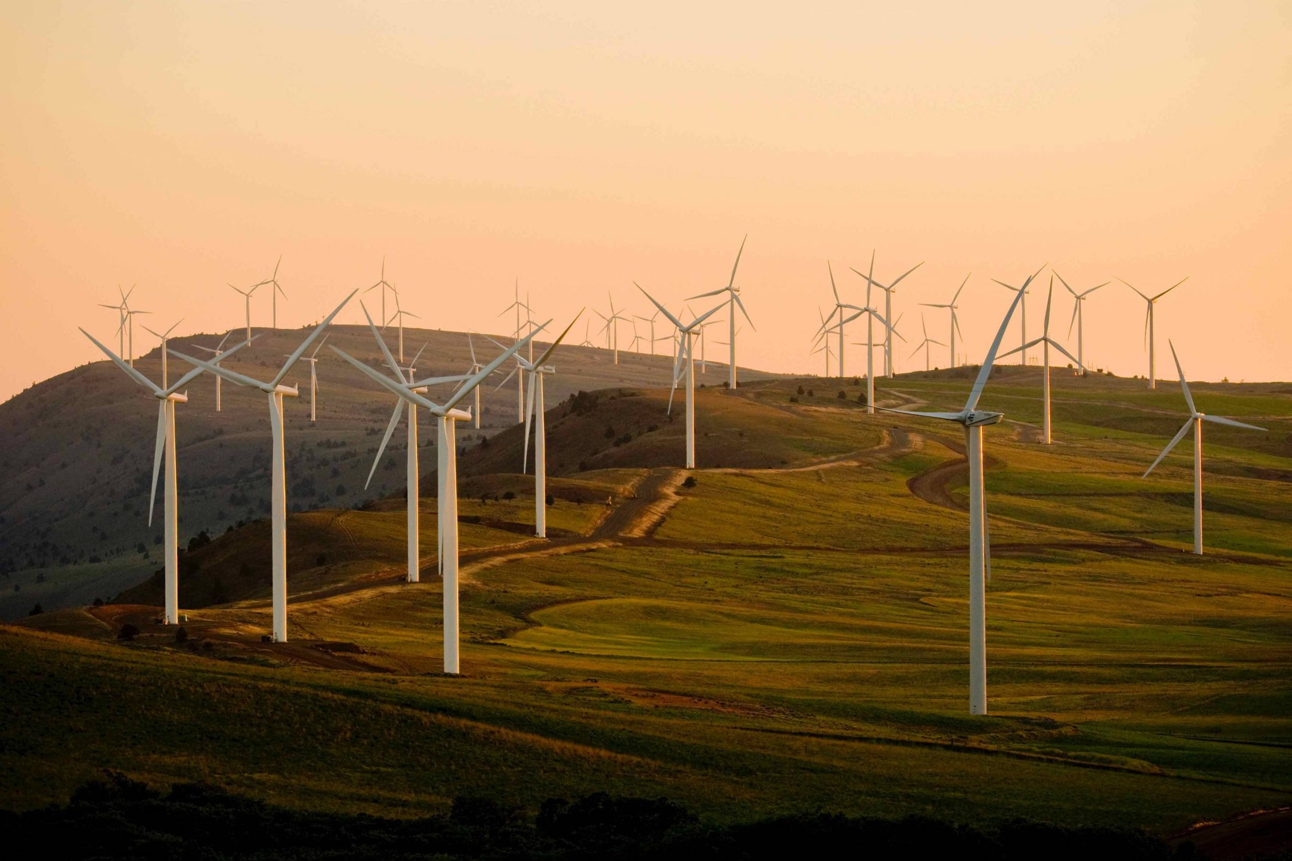
Choosing an installation site is critical. Extreme concern should be exercised in selecting a site for a wind-turbine installation. Considerable amounts of shear and compression normally occur in a horizontal wind stream as it travels over the topographical contours and rough surface of the Earth at any installation site. Meteorological data should be collected over several years to make sure that wind speeds of 6 to 15 m/s are available at operating heights of 20 to 30 feet, where wind speed is normally measured by anemometers. Shear generates lower wind speeds near the surface than at greater heights sufficient for free wind flow to occur. Furthermore, the free flow velocity at heights high enough from the surface to be unaffected by surface shear is significantly larger than that of the winds at the surface or at anemometer heights of 20 to 30 feet where wind speed is usually considered.

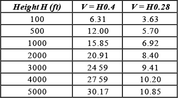
According to aerodynamics and fluid dynamic scientists, the wind speed near the surface of the Earth increases close to the 1/7 power of the turbine height over the surface of the ground, over open water such as a lake, river, or sea, and over flat plains as illustrated in Figure 1. It is clear that wind speed (V) varies as H0.4 due to high buildings, as H0.28 due to plants and homes, respectively. These values may not be valid in desert regions due to temperature variations within 20 feet above the surface.

Table 1: Vertical wind speed as function of height for various ground roughness factors.

Noise Level

Noise generated by wind turbines can be an annoyance, and the decibel (dB) intensity ranges from the slightly audible to causing discomfort. Scientists believe that doubling the power of a noise source by installing two wind turbines will increase the overall noise level by 3 dB.

It is important to clarify that any pain level from noise is dependent on the pitch of the blades and the components of sound generated by the wind turbine, including the wind over the rotor blades and the whirring of the generator. In addition, each sound component has a typical pitch, making it unique from the other sound generators. The noise measurements are dependent on the way the human ear recognizes sound by using a scale for the frequencies best heard. Noise level is considered in decibels (dB), the unit normally used to indicate noise levels. Wind turbines with two blades spinning downwind of a tower will make a characteristic “whop-whop” as the rotor blades pass behind the tower. This sound may be missed by standard noise-measuring equipment. It is interesting that many complaints about wind-turbine noise in California have been directed at two-bladed downwind turbines. If a customer selects this type of wind turbine, he may need to consider the inherent effects from low-frequency sound components.

Another element is the time duration over which turbine noise can be heard. City or county noise ordinances generally specify a maximum level that must not be exceeded over a specified time frame. Some cities and counties weigh the time duration over which the noise occurs at various levels and frequencies. This complicates the task of estimating the impact from the noise of a wind turbine. Compared to noise levels from trains or airplanes that emit high levels infrequently throughout the day and night, a wind turbine may emit far less noise but does so continuously. Some may find this aspect of the wind-turbine-based energy more annoying than noise generated by other energy sources.

Figure 1

Noise acceptance is affected by subjective factors. If your community is unhappy about high utility rates, the sound from a wind turbine may add to community unhappiness. Finally, the noise generated by a wind turbine must be placed within the context of noise levels from other sources. For example, if you live near an airport or a busy highway, a wind turbine will barely create a noise problem.

Another example is noise from the wind. If an installation is in a high-wind area, the wind-turbine noise may not be bothersome because the ambient noise level of the wind stream may affect the noise level generated by a turbine. It is important to distinguish the ambient background noise of an installation and the noise generated by the wind turbine. It should be the objective of the responsible authorities to limit increases in the total noise arising from a wind-turbine installation in relation to noise generated by other sources.

Ambient Noise from Installation Site

Studies performed by wind-turbine design engineers show the ambient or background noise from the nearby trees varies from 51 to 55 dB (A) at a distance of 40 feet. Under these wind-speed conditions, the noise from the nearby trees can cover the noise generated by a 10-kW wind turbine operating in the same wind situation. One must understand clearly the difference between the background noise and the noise generated by a wind turbine. The background noise level is subject to surface conditions, while the noise produced by a wind turbine is based on the blade parameters and number of blades in the rotor.

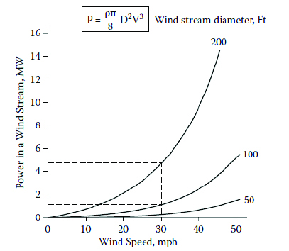
Noise capacity made by aerodynamic engineers indicates the ambient noise level from a 10-kW wind turbine is about 51 to 53 dB (A) at wind speeds of 11 m/sec [4]. The noise generated by the turbine varies from 54 to 55 dB (A) at a distance of 323 feet (100 meters) to 53 to 54 dB (A) at 643 feet (200 meters).The noise level estimates predicted by the European Wind Energy Association for 300-kW wind turbines indicate the noise from operation in a wind-speed environment of 18 mph will drop to 45 dB (A) within 200 meters. The overall noise level from 30 wind turbines of 10 kW each will be 45 dB (A) within 500 meters. (See Figure 2)

Figure 2: Noise level with distance.

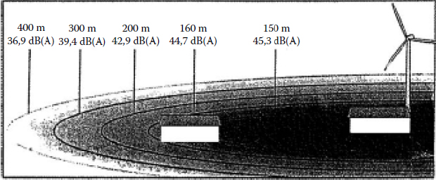
The noise estimates indicate no wind turbine, no matter how silent, can achieve levels better than the ambient noise. It is important to mention the difference between the ambient noise level and the noise level generated by a wind turbine determines most people’s responses. The main objective of the authorities should be limiting increases in the total noise to a level that should be acceptable to the residents in the vicinity of a wind-turbine site.

References

  1. S. Mertens, Wind Energy in Built Environments, 1989, Multi science, Essex, U.K., p. 16.
  2. R.E. Wilson, S.N. Walker, and P.B. Lissaman, Aerodynamics of Darrieus rotor, AIAA J. Aircraft, 15, 1023, 1976.
  3. S. Mertens, Wind Energy in Built Environments, 1989, Multi science, Essex, U.K., p. 79.
  4. A.J. Wortman, Introduction to Wind Turbine Engineering, 1983, Butterworth, Boston, p. 29.
  5. J.F. Walker and N. Jenkins, Wind Energy Technology, 2002, John Wiley & Sons, Chichester.
  6. O.L. Martin and J.Hansen, Aerodynamics of Wind Turbines, 2nd ed., 1992, James & James,London.
  7. Sen Ganguly SS and Das A. Renewable energy scenario in India: opportunities and challenges. J Afr Earth Sci 2016; 122: 25–31.
  8. The Government of India-Ministry of Power. Power sector at a glance All India, www.powermin.nic.in/en/content/power-sector-glance-all-India (2018, accessed 09 February 2018).
  9. Kar S and Sharma KA. Wind power developments in India. J Renew Sust Energ Rev 2012; 1157–1164.
  10. Goude A and Bülow F. Aerodynamic and electrical evaluation of a VAWT farm control system with passive rectifiers and mutual DC-bus. J Renew Energ 2013; 60: 284–292.
  11. Private Limited (Mnre Approved Channel Partner C). Iysert energy research Iysert vertical axis wind turbine, www.iysertenergy.com/vertical-axis-wind-turbine.html (2018, accessed 09 September 2018).
  12. Khan I. Review of wind energy utilization in South Asia. J Procedia Eng 2012; 49: 213–220.
  13. Tim B. Australia–India, February Electricity sector transformation-in India a case study of Tamil Nadu. Report. The Institute for Energy Economics and Financial Analysis (IEEFA)–Energy Finance Studies, 2018.

The future of offshore wind is big — literally

0

Offshore wind turbines and wind-power plants are getting bigger every year, a trend that already helps offshore wind reduce costs all over the world. But while recent research suggests that costs will continue to dip as wind turbines and plants get bigger, the amount of these potential savings and whether there’s a maximum size where costs plateau remains unclear.

Now, in a recent study published in Applied Energy, researchers from NREL conducted one of the most comprehensive analyses currently available of the average cost per megawatt-hour to develop and maintain offshore wind-power plants and how those costs could change if current trends toward larger plants and turbines continue.

To do that, the team combined three models and found that larger wind turbines and power plant projects alone can reduce a plant’s average total cost per megawatt-hour over its lifetime (also known as LCOE) by more than 23 percent relative to the average fixed-bottom offshore wind power plant installed in 2019.

“We expected to see the costs decrease,” said Matt Shields, an NREL researcher who leads the lab’s work on techno-economic analysis of offshore wind energy and headed the study. “But I was a little surprised about the magnitude. That’s really a game changer.”

Offshore wind-energy plants are part of a complex supply chain in which manufacturers design various parts, expert laborers make and assemble these parts at multiple ports, and specialized vessels transport the turbines offshore for installation. (Courtesy: Shutterstock)

Investment Confidence

The team’s data provides a valuable touchstone. Now, the growing offshore wind industry can more confidently invest in the supply chain needed to build bigger turbines and larger projects — a chain that is not yet sufficient to achieve the Biden administration’s goal of deploying 30 GW of offshore wind energy by 2030.

The study was funded by WETO and coauthored by NREL researchers Philipp Beiter, Jake Nunemaker, Aubryn Cooperman, and Patrick Duffy.

Offshore wind-energy plants are part of a complex supply chain in which manufacturers design various parts, expert laborers make and assemble these parts at multiple ports, and specialized vessels transport the turbines offshore for installation. Every link in this chain comes with a cost that changes based on project and technology size and type. And, once the wind turbines are installed, O&M costs vary, too. But these costs don’t necessarily increase with size.

Reducing Costs

For example, a power plant that upgrades to larger wind turbines will need fewer machines to generate the same amount of energy. Fewer turbines mean fewer installation vessel trips and less overall maintenance. Both reduce costs. And yet, because larger wind turbines and power plants often need bigger foundations and more cables to transfer energy back to shore, they cost more money up front. These conflicting cost trends make it hard to determine how wind-turbine and power-plant upsizing affect total cost and energy output.

To see if bigger really is better, Shields and his team blended three models for:

  • Balance-of-system costs (i.e., all capital costs — for foundations, cables, and installation — except for the wind turbine).
  • O&M costs.
  • Annual energy production.

NREL researchers designed two of the models — the open-source Offshore Renewables Balance-of-system Installation Tool (ORBIT) and the FLOw Redirection and Induction in Steady State (FLORIS) tools. To evaluate operation and maintenance costs, the team used the commercial Shoreline O&M Design model.

Then, the researchers used the models to compare the cost of a representative 2019 fixed-bottom offshore wind-power plant, which used 100 6-MW wind turbines for a total capacity of 600 MW, with various wind turbine and power plant sizes — up to a maximum of 20-MW wind turbines with a plant capacity of 2,500 MW. The models showed that scaling up both wind-turbine and power-plant size can reduce balance-of-system and maintenance costs through economies of scale (e.g., spreading export cable costs over larger projects) while reducing losses from wakes. Wakes, turbine-made turbulence that can decrease power production of downstream turbines, decline as turbines are spaced farther apart in larger and larger wind plants.

To show that building bigger offshore wind plants could reduce overall costs, NREL researchers designed one of the most comprehensive analyses of the total cost needed to develop and maintain offshore wind power plants currently available. (Courtesy: Lyfted Media for Dominion Energy)

More Research Needed

Combined, these savings can add up to more than 23 percent. Still, more research is needed to achieve these savings, determine whether and how this reduction applies to floating offshore wind-power plants, and learn whether the “bigger is better” tenet has a limit. Cost savings could plateau at a maximum wind-turbine or power-plant size.

Right now, the wind industry can’t achieve that 23 percent. No manufacturer can build a 20-MW wind turbine — yet. And even when they can, the rest of the supply chain will need to catch up, too. For example, today’s vessels and ports are designed to install wind turbines of 12 MW or less.

Shields and his team plan to take a closer look at how innovations in technology and the supply chain might help further reduce costs in the future. In the meantime, they are working on creating a supply chain road map to find missing links.

“We need to jump-start the domestic supply chain as quickly as possible to minimize project risks, make projects even cheaper, create local jobs, and grow a more sustainable industry,” Shields said. “We want to build offshore wind-power plants to reduce our carbon footprint, and we can do it in such a way that we are positively impacting local economies.”

The supply chain must grow — quickly — to meet the 30-GW-by-2030 goal. And this study can help each link plan for a bigger future. “That’s going to be a huge challenge for us over the next decade,” Shields said. “But it’s one that’s worth investing in.”

Siemens Gamesa to provide 84 wind turbines in India

Siemens Gamesa has secured an order in India from Ayana Renewable Power Six Private Limited to supply a 302-MW project, providing another boost to the country’s wind-energy drive. A total of 84 units of the SG 3.6-145 wind turbines will be installed for the project in the Gadag district, Karnataka State.

“We are happy to announce this new deal with Ayana Renewable Power, one of the fastest growing renewable Independent Power Producers (IPPs) in India,” said Navin Dewaji, India CEO of Siemens Gamesa.

“This order significantly helps us as we gear up for the next growth phase for Siemens Gamesa in India. With the SG 3.6-145, a turbine made for India, we are confident we are delivering better value for our customers.”

Ayana first partnered with Siemens Gamesa in 2019 for a 300-MW solar farm in the state of Rajasthan and has 3 GW of renewable energy capacity under various stages of development and operation across several Indian states. Ayana won this project in the SECI ISTS Tranche X tender and will develop the required infrastructure for this windfarm, planned in the state of Karnataka.

Siemens Gamesa launched this new turbine in 2020 despite an ongoing pandemic and announced its first orders in July 2021 for 623 MW. Turbines for this project will be supplied from the manufacturing plants in India and the project is expected to be commissioned in 2023. The SG 3.6-145 wind turbine is an extension of the SG 3.4-145.

Siemens Gamesa has operated in India since 2009, and the base installed by the company recently surpassed the 7-GW mark. The company has one blade factory in Nellore (Andhra Pradesh), a nacelle factory in Mamandur (Chennai, Tamil Nadu), and an operations and maintenance center in the Red Hills (Chennai, Tamil Nadu).

More info www.siemensgamesa.com

Titan Wind Energy chooses Haeusler for Shanghai facility

Titan Wind Energy has chosen Haeusler for its facility near Shanghai. Haeusler’s EVO machines have accessories adapted for the construction of wind towers, including manipulators for conical and cylindrical shells, as well as an upper support adapted for wind tower production and a swiveling infeed roller table.

All machines are CNC-capable, which allows a fully automated production with short cycle times.

More info www.haeusler.com

Pronomar dries work clothing, equipment

Pronomar drying systems can be a big help for workers on roads, urban green spaces, agriculture sites, and ships.

Pronomar systems can be helpful for workers in winter conditions. (Courtesy: Pronomar)

Pronomar’s rounded hangers can dry PPE including boots and gloves, jackets, trousers, coveralls, suits, helmets, masks, life vests, and other types of equipment.

By maintaining a correct temperature during drying, the material and quality of the PPE is gently and quickly dried, resulting in longer life for the clothing.

Pronomar’s drying systems include Eledry, using electrically heated hangers to dry footwear and gloves. The AIR system features quick drying, while the WATER system is most suitable for new build sites.

More info www.pronomar.com

James Fisher launches decommissioning business

James Fisher recently launched James Fisher Decommissioning (JF Decom) to support customers in the renewables and oil and gas markets.

JF Decom will provide customers with a dedicated team to provide delivery in complex projects such as subsea infrastructure removal; structural removal, well severance, and well abandonment.

With one of the world’s largest fleets of decommissioning tooling and in-house design and engineering capability, JF Decom can support the rise in decommissioning projects to deliver cost and time saving solutions critical to achieving regulatory guidance of a 35 percent reduction in decommissioning costs, a target mapped out by the Oil & Gas Authority in 2016.

JF Decom’s services include the well abandonment tool SEABASS that provides a cost effective and quicker alternative to rig-based solutions when abandoning category 2 wells, due to its ability to deploy from a vessel of opportunity and work in any water depth.

“JF Decom is also dedicated to ensuring that decommissioning is conducted as sustainably as possible by restoring the seabed to its natural state,” said Jack Davidson, JF Decom managing director. “With our noise attenuation tools such as Bubble Curtains, we can also minimize environmental impact to marine life during decommissioning works and ensuring we provide environmentally responsible services is something that is at the forefront for JF Decom.”

JF Decom and JF Renewables will be able to work independently or collaboratively to support the drive to net zero by providing full support services to the oil and gas and renewable markets in the installation, maintenance, and decommissioning of assets.

More info www.jamesfisherrenewables.com

NewHydrogen to provide green hydrogen generators

NewHydrogen will provide green hydrogen generators to intermittent renewable power sites, such as wind and solar farms. The Massachusetts-based Verde LLC will provide NewHydrogen with hydrogen generation systems.

“We are very excited about our new business relationship with Verde and our plan to partner with operators of intermittent renewable power sites, such as wind and solar farms,” said David Lee, CEO of NewHydrogen.

NewHydrogen is developing technology to reduce the use of rare earth metals in electrolyzers. (Courtesy: NewHydrogen)

NewHydrogen is targeting wind and solar farms that produce excess solar and wind energy during certain times of the day. This power can be used to run an electrolyzer (the primary component in a hydrogen generator) that converts water into green hydrogen, which is distributed in pipelines and converted back into electricity when needed. This green hydrogen can be stored in tanks and underground caverns, forming a network that can energize industry and back up electric grids.

“For NewHydrogen, this is a major leap forward,” Lee said. “By owning and controlling the hydrogen generators at these sites, we will be able to move very rapidly to demonstrate the economic viability of this approach, as well as new technology currently under development including our breakthrough catalysts.”

The goal of NewHydrogen’s sponsored research at UCLA is to lower the cost of green hydrogen by eliminating or reducing the use of precious metals in electrolyzers.

Electrolyzers currently rely on rare-earth materials such as iridium and platinum, which often accounts for nearly 50 percent of the electrolyzers’ cost.

More info www.newhydrogen.com

WindCube Nacelle Lidar earns full classification

Leosphere, a company that specializes in developing, manufacturing, and servicing turnkey wind Lidar instruments for wind energy, recently announced that WindCube® Nacelle is the first nacelle Lidar to receive full classification according to the new IEC standard for nacelle-based Lidar.

The classification paves the way for increased adoption and acceptance for power performance testing (PPT). (Courtesy: National Renewable Energy Laboratory )

Latest enhancements to the WindCube Nacelle deliver simplified Lidar system and data management with the cloud-based WindCube Insights — Fleet.

Rotor equivalent wind speed Lidar data provides rotor-averaged wind speed, enabling more detailed analysis of most modern, large rotor turbines.

An integrated weather sensor directly mounted on the Lidar provides air pressure, temperature, humidity, and rain and hail data.

More info www.windcubelidar.com

Aqueos supports growth of offshore wind energy

Aqueos has been a part of every offshore wind-energy project in the U.S. One project that showcases Aqueos’ merit is the Virginia Coastal Wind (VCW 01) Project.

When the Bureau of Ocean Energy Management (BOEM) issued consent to Dominion Energy to the first wind-energy research lease in U.S. federal waters, the bureau formed a chain of expertise that led to Aqueos. Dominion partnered with Danish multinational company Ørsted, which contracted Aqueos’ client, Subsea 7, to supply and install cables for the Virginia Coastal Wind (VCW 01) Project.

Dominion partnered with the Danish multinational company Ørsted, which contracted Aqueos’ client, Subsea 7, to supply and install cables for the Virginia Coastal Wind (VCW 01) Project. (Courtesy: Aqueos)

Aqueos assisted by providing project management and engineering services, as well as offshore support for the export cable nearshore installation.

Ørsted required divers to be IMCA-certified with similar experience. Aqueos personnel were already DNV-certified, IOGP approved, and IMCA/ ADCI members. Aqueos assisted by developing HSE, quality, engineering, and management procedures. Subsea operations included the excavation of the HDD bore hole exit location, transmission cable pull-in, grouting operations, and survey activities.

Powered by years of subsea experience in the offshore oil and gas sector, the Aqueos team is now prepared for more wind-sector work — and is well positioned to deliver future wind-energy projects to the Northeast and the Gulf of Mexico and the West Coast regions of the U.S.

More info aqueossubsea.com

Collett completes deliveries to Scotland wind farm

Collett has completed the transport of components for the Twentyshilling Wind Farm in Dumfries & Galloway, Scotland. Over a period of 14 weeks, Collett moved components from King George V Dock to the site.

Collett moved the components for each complete turbine: the three tower sections, three blades, nacelle, drive train and hub. It would require specialist transport logistics for the 170-mile journey to site.

The team made several route modifications. Two miles from the construction site, on approach to the wind farm, the loaded 57-meter blades would be unable to facilitate the necessary left turn to access. A turning head was constructed at Eliock Bridge to provide the required clearance to allow all 27 of the blades to safely navigate the turn.
Working on a two-day delivery schedule, with three deliveries per convoy, Collett’s specialist fleet delivered the 81 individual components.

The team employed super wing carriers to transport the 57-meter, 14.9-ton blades. For the other components, the 67-ton, 25-meter long bottom and 44.5-ton, 26-meter middle towers used specialist clamp trailers, while the remaining components, the top towers, nacelle, drive trains, and hubs were transported using 5- and 6-axle step-frame trailers.
All components traveled under Collett’s Code of Practice escort vehicles, with police escorts in attendance for the blades, tower sections, nacelles, and drive trains.

The nine Vestas V117 140-meter tip turbines are expected to be fully operational in early 2022.

More info collett.co.uk

Collett acquires Plant Speed turbine equipment

Collett & Sons Ltd recently agreed to a deal with Plant Speed to have its specialist wind-turbine equipment join the Collett fleet. Taking the decision to remove themselves from the wind-energy industry and focus more on their haulage operations, Plant Speed is focusing more on haulage operations, and Collett is acquiring the entire Plant Speed fleet of super wing carriers, extendable trailers, and lift adapters.

Collett has acquired Plant Speed’s entire fleet of super wing carriers, extendable trailers and lift adapters. (Courtesy: Collett)

“With several projects scheduled and currently under way, this move sees Collett strengthen our market position,” said Managing Director David Collett.

“Having worked in the renewable-energy industry for many years, the acquisition of this new trailer equipment is a decisive move for Collett, and one which significantly increases our wind-turbine carrying capabilities.”

Collett’s wind-turbine fleet expansion includes Nooteboom super wing carriers, quadruple extendable blade trailers, and lift adapters, alongside several specialist adapters including gyrostat tables, loading beds, and tower hooks.

As a well-established operator in the wind-energy industry, the addition of this new equipment increases Collett’s carrying capacity and adds to its already diverse fleet, providing a definitive range of specialist equipment with which to undertake wind-farm development projects.

“Having worked closely with Collett in the past, the decision to amalgamate our fleet in to theirs was an easy one to make,” said Paul Lomas, Plant Speed’s managing director.

More info collett.co.uk

Crosby Group innovating floating offshore wind

It has been nearly two years since The Crosby Group, a global leader in lifting, rigging, and material handling hardware, completed the acquisition of Feubo, a specialist provider of offshore mooring components for the oil and gas and wind-energy markets.

Crosby Group acquired Feubo, a specialist provider of offshore mooring components for the oil and gas and wind-energy markets. (Courtesy: The Crosby Group)

The purchase included Feubo’s facility in Hattingen, Germany, that has continued to serve as a center of excellence for mooring components. It is equipped to support the installation and safe operation of floating wind turbines, typically mounted on a floating structure that allows the turbine to generate electricity in water depths where fixed-foundation turbines are not suitable.

The Hattingen facility is also a focal point for key testing, engineering, and innovation, that notably led to the launch of the HFL Kenter, a high fatigue life shackle, based on the popular Crosby Feubo NDur Link.

“The floating wind industry remains relatively embryonic, and it needs product engineering and innovation partners to collaborate on products that can improve safety and reduce costs,” said Mike Duncan, business development manager at The Crosby Group. “The HFL Kenter for temporary mooring is just an example of how a new product can be developed and broadly deployed within an industry to achieve industry goals.”

As Duncan alluded to, the HFL Kenter is an accessory used for temporary and mobile mooring applications, such as rigging and anchoring mobile offshore drilling units (MODUs) or vessels. It represents the latest state-of-the-art evolution of a shackle concept that is more than 100 years old. Finite Element Analysis, a method of numerically solving differential equations in engineering and mathematical modeling, was used to identify stress hot spots and re-engineer the product.

“In fatigue comparison tests in simulated marine environments, we were able to show that the Kenter boasts eight times more cycles,” he said. “This has allowed us to show the floating wind sector our ability to engineer, innovate, and deliver product of high quality and proven fatigue life, for their specific, demanding applications.”

Duncan reiterated the capabilities of The Crosby Group’s center of excellence for mooring in Hattingen, Germany, which boasts static and dynamic testing machines that test mooring chains and components up to capacities of 60,000 kN, as well as fatigue testing in simulated marine environments. The facility can test and validate in real-time the fatigue life of components in association with DNV GL Type Approval Certificate, acknowledging that its equipment meets the rigorous standards of the global quality assurance and risk management company for their use offshore.

More info www.thecrosbygroup.com

Conversation with Matthieu Boquet

Leosphere, a Vaisala company that specializes in developing, manufacturing, and servicing turnkey wind Lidar instruments for wind energy, recently announced, in collaboration with DNV, that its WindCube® Nacelle is the first Lidar to receive full classification according to the new IEC 61400-50-3 standard for nacelle-based Lidar. Wind Systems recently discussed this achievement with Matthieu Boquet, the company’s head of Market and Offering, Renewable Energy.

What is the WindCube Nacelle and what can it do for the wind industry?

WindCube Nacelle is a laser-based, remote-sensing device that can be easily installed on top of a wind turbine. It measures the incoming wind to deliver an accurate understanding of the performance of the wind turbine, making it possible to verify that it performs properly and delivers the power that is expected. It is quite easy to deploy on a wind turbine where it continuously measures the wind in front to measure the power curve of the wind turbine. This is a very important parameter as it indicates the efficiency of a wind turbine. The accuracy of this measurement is essential in understanding if there is any under-performance. If the measured power curve is lower than the expected power curve, then you would have to take some corrective actions. And if it’s correct, then you know that your wind turbine is delivering what is expected and you are on track to meet your goals.

WindCube Nacelle is a laser-based, remote-sensing device that can be easily installed on top of a wind turbine. (Courtesy: Leosphere)

How does the WindCube Nacelle differ from other Lidar systems?

WindCube Nacelle is now approved as a standard instrument for power performance testing (PPT). PPT is the action of measuring the power curve of a wind turbine. The WindCube Nacelle is the first of its kind to be approved by the highest industry standard that exists — the IEC standard — and is a classified instrument to perform state-of-the-art power performance testing. WindCube Nacelle has a proven track record as it has been used for years by many turbine manufacturers and wind-farm developers and operators. It is already included in many developer and manufacturer turbine supply agreements.

Many of our customers say it is the most accurate instrument and the easiest to use and deploy. It has several mounting options, so it’s very versatile and can be installed on any type of wind turbine.

The WindCube Nacelle is the most trusted on the market thanks to its long track record and now bolstered by this IEC classification. And, in the wind industry, trust in wind data is critical. Our WindCube Nacelle has been installed on more than 500 wind turbines, and it has really helped to secure its proven performance and ease-of-use.

How did Leosphere’s collaboration with DNV come about?

We have collaborated on Lidars with DNV for many years — not only the WindCube Nacelle but with our entire suite of Lidar devices, designed for all stages of a wind-farm project whether onshore or offshore. Our collaboration with DNV is fundamental for industry adoption of Lidars and defines the best practices for using Lidars. The classification that we have performed with DNV was just a natural next step thanks to all the projects that we have performed with them so far.

DNV works regularly with all of our Lidars, including WindCube Nacelle, for the calibration of the devices. This is something that they do all year round, as Lidars have to be calibrated for specific measurement campaigns. This is not the case for every campaign but in the case of warranty power curve verification, the device has to be verified by a third party. We have been collaborating on that with DNV and other trusted third party experts.

What are the advantages for the WindCube Nacelle receiving that full classification according to the new IEC 61400-50-3 standard?

With the IEC classification, the WindCube Nacelle is officially an industry-accepted instrument for PPT. Before that, only met masts were accepted by the IEC Standards for verifying the performance of a wind turbine. Met masts are not easy to deploy, are expensive, and cannot be repurposed for new campaigns. For power performance testing, you only need the instrumentation for three to six months. Deploying, installing, and erecting a met mast just for conducting PPT is not efficient or cost effective. Now, with the new IEC standard and the WindCube Nacelle classification, you have a really efficient alternative solution to verify wind turbines and maximize wind-farm energy production.

Why is it important to have accurate and reliable power performance testing?

It’s important to have accurate PPT, but it’s also important first to make PPT. Because of the difficulty and the cost of using a met mast, only a few wind turbines can be tested and mostly only during the commissioning phase of the wind farm — not during the 20 or 25 years of operation. With so few tests, you cannot be sure that your wind farm is delivering at the right level of performance, nor have the diagnostics to take corrective actions and improve your energy production. It’s important to have this kind of solution to optimize performance and maximize your profits. Then, of course, the measurement solution has to be accurate; the more accurate the data is, the better the analysis.

What new enhancements does the WindCube Nacelle include, and how will they provide richer data options while making the system easier to use?

In addition to the IEC Classification that we just obtained, we also introduced a set of new mounting options to facilitate the installation of the Lidar on a variety of wind-turbine nacelles, and there is a large variety of wind-turbine nacelles out there. The WindCube Nacelle now also supports an integrated Vaisala PTH weather sensor, which measures pressure, temperature, and humidity. This additional data augments PPT data, providing valuable insights into overall wind-turbine performance. The WindCube Nacelle is now also compatible with our web-based fleet-monitoring solution, making remote system configuration, monitoring, and data access easy, whether you have a single Lidar or a fleet.

The Lidar can now measure the rotor equivalent wind speed (REWS), which is an additional output from the Lidar. It comes in addition to the already existing hub height wind speed, which is, in most of the cases, used for power performance testing, but we are also providing this alternative value in order to better understand the behavior of turbines with large rotors.

Finally, it is completed by WindCube Insights Analytics software that enables a very quick calculation of the power curve of the wind turbine, following the new IEC standard, so it’s a very simple process to analyze the data coming from the WindCube Nacelle for measuring the power curve.

How will the WindCube Nacelle’s advanced enhancements further establish Leosphere and Vaisala as the go-to source to empower wind-industry players?

There’s continuous improvement in our industry to further reduce the cost of wind energy. We’re glad that we can contribute to this by delivering modern wind-measurement solutions that provide accurate data while improving safety for wind-farm employees. We’re also happy to support the standardization of new, better practices to improve wind-industry sustainability, and we expect that more PPT will be performed following an accurate and cost-efficient process as this is fundamental to optimize the performance of wind farms and the cost of renewable energy.

More info www.windcubelidar.com

Malloy Electric: Developing solutions for a growing industry

0

Bearings found in wind turbines come in an amazing variety of sizes, and when a bearing starts to show wear or fatigue, replacement time is of the essence in order to avoid any costly downtime.

When this happens, it’s critical that owner-operators can get upgraded replacements as quickly as possible, and that’s where Malloy Electric enters the picture.

“We carry a large inventory of wind-specific bearings covering most of the installed models in the U.S.,” said Cory Mittleider, wind business unit manager for Malloy Electric. “We support operators, service providers, and even OEMs. Our inventory and production pipeline allows us to ship immediately for an urgent need or supply on a schedule for repair campaigns and repower projects. We also have critical storage warehouses where we store and care for customer-owned assets until dispatched.”

Malloy Electric strives to be technical experts in three categories: motors, electrical, and mechanical, according to Mittleider, and that expertise is essential to Malloy choosing the proper products to stock, as well as how many.

A blade bearing teardown. (Courtesy: Malloy Electric)

Malloy’s wind division

“Our wind division has the same philosophy with an emphasis on mechanical,” he said. “We’ve been involved with failure analysis and upgrades on most bearing applications in wind turbines including pitch-motor bearings that fit in your hand, gearbox bearings that range from 100 millimeters to 900 millimeters, main shaft bearings that weigh 3,000 pounds, and blade bearings that are nearly three meters in diameter.”

As part of Malloy’s electrical division, the company is also heavily involved with making sure obsolete components are addressed quickly, according to Mittleider.

“There have been multiple projects now where either a breaker or a contactor that’s used in the wind turbines becomes obsolete,” he said. “They can no longer either replace it or cost effectively repair it. Our electrical group, combined with our UL 508A panel shop, has developed retrofit kits where we use a new product, current generation breaker, and then adapt the mechanical fitment, and electrical connection interface to the existing design.

Because, unfortunately, when electrical manufacturers obsolete old product to roll out new ones, the fitment’s never the same. It’s always a different shape, different size, or it mounts in a different place. That’s where we’ve used our electrical group to look at that new product and develop retrofits to make it as easy as possible for those in the field.”

Investigating problems

Being a bearing distributor, Malloy spends a lot of time doing investigations, which, according to Mittleider, makes the company a little different than most distributors.

“We have a great depth of knowledge, and we have many engineers on staff,” he said. “We want to be super technically focused and know what we’re selling. We don’t just grab a part number and say, ‘Hey you failed one of these, can I get you another?’ Everybody knows that’s not the way to solve a problem. We like to ask why? Why did it fail? Let’s discuss and investigate that. And that’s why we’re doing the tear downs and the failure analysis. The way to solve the problem is to ask more questions and understand why it failed. How can it be improved — whether it’s the component, the bearing itself, or one of the other outside factors that need to be improved on.”

Malloy Electric works with some of the largest bearing manufacturers in the world, and because the company has such expertise with systems failures, it often plays a critical role in developing solutions, according to Mittleider. Certain bearings Malloy will send back to the manufacturer’s lab, but other bearing types can be dismantled and analyzed in Malloy’s in-house facility in doing those investigations.

“We stay in very close correspondence on these applications with those manufacturers and say, ‘This is what we’re learning; these are the measurements we’re taking; this is the feedback we’re getting from the site that sent us the failure; we discuss the best way to use these findings to improve the bearing in this application,” he said. “But typically, with a bearing manufacturer, we’re looking at what we can do to make that bearing live in environments and applications that we know are difficult.”

Malloy’s large inventory of wind specific bearings. (Courtesy: Malloy Electric)

Wind-site visits

To that end, Malloy Electric’s experts visit a lot of wind sites to discuss applications with the operators, according to Mittleider.

“We do visit the sites a lot, but we don’t climb,” he said. “We support either the operators that self-perform those scopes of work during replacements or the service providers hired by those operators. We do use our site visits to collect information and sometimes even collect the samples and bring them back on a trailer or in the back of a pickup assize dictates. Our tear downs and investigations are done in either our shop, a service provider’s shop, or the manufacturer’s shop depending on the application.”

Getting into wind

For a company that is constantly striving to make sure wind turbines are working with the best parts, it’s a bit ironic that Malloy’s entry into the wind market is somewhat serendipitous. “It wasn’t maybe a conscious decision or a push to get into wind,” Mittleider said. “It was more of a pull into it.” Even though it started life as an electric motor repair company in 1945, Malloy Electric entered the wind industry in the late 1990s when a wind-farm operator who was experiencing premature failures on generators came to Malloy for help, according to Mittleider.

“It was our success in other industries and the people that were in those other industries who knew us for electric motor repair, both big and small,” he said. “They worked at that wind farm, and they realized the generator was pretty similar to an electric motor. They had good experience with Malloy in these other industries, and they thought we should be the people to talk to. We were able to help develop solutions for these failure modes and dramatically increase reliability of these generators.”

That job was only the beginning of Malloy’s wind experience, as well as forming the basis of how the company works with its customers, according to Mittleider. “The first step is to collect as much information as possible about the failure modes, application history, and what work they’ve been able to do on their own,” he said. “Typically, the next step will include getting at least one failed sample for investigation. We learn a lot about the failures from an inspection of a failed part.

For example, we’ve seen gearbox bearings come back with a particular failure mode described, but once thoroughly inspected at the lab, we find more below the surface. This deep evaluation and cooperation with the bearing manufacturers allows us to design a new part with upgraded geometry, materials, heat treatments, and coatings targeted at solving the whole problem.”

An SEM image of failed gearbox planet bearing. (Courtesy: Malloy Electric)

Failure analysis of blade bearings

That type of hands-on experience also applies to Malloy’s approach to dealing with failure analysis, according to Mittleider, particularly when it comes to blade bearings. “In the case of blade bearings, we’ll often be notified of the field observations such as: It’s leaking; there are pieces sticking out, or there’s a crack,” he said. Once the part is brought to Malloy’s facility, it gets cleaned up, then it’s torn down, dismantled, and marked, according to Mittleider.

“We get a chance to separate and open the bearing, which most operators and service providers don’t have either time or capabilities to do themselves,” he said. “They never get a chance to see inside. Once we see inside ourselves, we learn a lot more than can be learned in the field. For example, we have inspected blade bearings that were replaced because of one failure mode, but once opened, we found additional failure modes previously unknown. This type of investigation and investment in hands-on education helps us solve the problems in the most comprehensive way possible and can also help avoid introduction of new failure modes when implementing a solution.”

Failure analysis with blade bearings is often a bit different, according to Mittleider.
“Blade bearings are a specific type of bearing called a slewing bearing,” he said. “It’s typically a large diameter with rings that aren’t terribly thick. Respective to the diameter, they’re actually pretty thin in cross section. In most applications, there are filling plugs in the outer ring of the bearing. And that’s part of the difficulty and the limitation that the operators and service providers have in the field. First of all, they’re big, and they’re heavy, and you’ve got to be able to flip them over to get to both sides. But then you have to have some special tooling to disassemble. The procedure is elaborate and time consuming and a very messy process.”

Mittleider said he is particularly proud of how Malloy has been able to handle blade bearing teardowns over the company’s 24-year history with the wind industry. “These bearings are very large, typically quite dirty, and not easy to handle,” he said. “We have established a process of cleanup, teardown, and thorough inspection that has proven to provide us a great understanding of the life the bearing lived and point us to the root cause of failure. Working with these failures from the field is a dirty and time-consuming job but has offered an incredible education to the team at Malloy and to the operators that we’ve worked with.”

An exploded view of a blade bearing. (Courtesy: Malloy Electric)

Working with operators

As new turbines continue to grow in size and push the limits of their components, Mittleider emphasized it’s even more important for Malloy to have the ability to go that extra mile for its customers’ repair challenges.

“We work closely with operators and service providers to learn about these as soon as possible so we can start working on our solutions for the next generation equipment,” he said. “Another part of this is the aging fleet. These older turbines have motors in need of refurbishment, still have need for replacement bearings, and in some cases, have subcomponents that have been obsoleted by the manufacturer such as breakers. In these cases, we can offer motor repairs, replacement bearings with current generation upgrades, and retrofit kits for obsolete breakers.”

That dedication to detail has been a large part of what has kept Malloy Electric’s customers coming back, and as the company continues into the future, Mittleider said the company will keep offering next-level expertise.

“The wind industry changes very fast; even in the last few years, we’ve seen changes in turbine design, OEM consolidation, and improvements in end-of-life recovery such as blade recycling,” he said. “Malloy will continue to develop new solutions and expand our inventory to support this growing industry.”

More info MalloyWind.com

Constructing a drag-based wind turbine

0

Due to the current technological evolution trend, the use of renewable energies seems to be the best suited solution for environmental protection against pollution. This article aims to present the methodology used for the manufacturing and assembling processes of a drag-based, vertical-axis wind turbine, the steps for both processes being addressed broadly. The manufactured vertical-axis wind turbine can successfully function in wind conditions with speeds of up to 16m/s and manages to provide up to 5kW of power. The manufacturing materials used for the execution of the blades include metal sheets, mounted on a structural frame for better stiffness.

The wind-turbine rotor is comprised of three blades installed on a shaft connected to a gearbox, which will transfer the torque to the permanent magnet generator. The whole process is described in the article, and the result consists of the installed turbine ready to function in real-environment operating conditions. The work carried out within this article is relevant to the general know-how regarding wind-turbine manufacturing and installation, as the authors highlight the main impediments they had to overcome when developing, executing, and installing the described model.

Figure 1: Lenz blade components.

1 Introduction

Considering the worldwide energy scenario, it is safe to assume that in the next few years, most countries will face massive attempts to progress from common energy sources to renewables. This statement is reinforced by international major steps in the direction of green energy, supported by programs such as the European Green Deal [1] or by documents as the Paris Agreement [2]. Wind energy represents the second most efficient renewable source of electrical power, according to the data provided in the “Renewables 2019 Global Status Report” [3].

The extraction of kinetic energy from the wind and its transition into mechanical or electrical energy is realized using specifically designed systems for this task. Such systems are commonly called wind turbines and are divided into two large categories according to the direction of the rotating shaft: horizontal-axis wind turbines (HAWTs) and vertical-axis wind turbines (VAWTs). The two are compared in [4], the main highlights being that HAWTs can produce larger amounts of energy compared to VAWTs, but they need a specific work environment (isolated areas with high wind speeds), whereas VAWTs are more efficient in low wind velocities and in turbulent flows, being suited for installation in urban areas and adjacent zones.

Figure 2: Lenz blade assembly.

In order to improve the efficiency of VAWTs and to help them surpass the performances of HAWTs, new configurations have been developed and tested. Most common configurations include Savonius, Darrieus, and H-Darrieus wind turbines, and new geometries have been developed derived from these, such as the Crossflex wind turbine, combined Savonius-Darrieus rotor, Zephyr turbine or Lenz [5]. This article describes the manufacturing process of the latter configuration, with an emphasis on the used methodology, materials, and equipment.

The Lenz wind-turbine geometry is derived from a combination between the Savonius and Darrieus type and is better suited for functioning in reduced wind speeds. The advantages of a Lenz type VAWT include low-cost fabrication, as its design is not very complicated, and is reliable with an improved starting behavior and good performances in low winds [6]. A mathematical model for calculation activities that present as an outcome the geometric parameters for a Lenz turbine is described in [7]. The design procedure for this type of turbine is discussed, and future work includes the manufacturing of such a model, with applications in urban areas. In [8], a Lenz VAWT with three blades was designed and manufactured using aluminum sheets.

Figure 3: The arm system used for supporting the blades.

The system was validated through an experimental study. Furthermore, the model was tested with and without deflector vanes used as a method to control air flow direction and optimize the baseline geometry. The study concluded a deflector system can improve the overall performances of the turbine when installed properly, with the angle of instalment having a great influence on the turbine’s efficiency. Some experimental campaigns, such as the one presented in [9], study the blade number influence for the discussed configurations.

Figure 4: Blades installed on the arm system.

The authors design and manufacture a five-bladed Lenz wind turbine, using aluminum sheets and fiberglass. Sivamani et al. experimentally investigate a two-stage Lenz wind turbine with three blades, for a velocity range from 5 to 7 m/s. As a result, they discuss power and moment-coefficient variations [10]. The model investigated was manufactured using a solid mild steel material for the shaft and disks, whereas, for the blades, plywood and aluminum sheets were used.

Figure 5: Lenz wind-turbine model and assembly.

The most common materials for the manufacturing of the blades for the discussed turbine geometry include thin metallic sheets (often aluminum alloy) and steel for the other components, as can be concluded from the discussed papers. The fabrication methods frequently include cutting processes and rolling.

In this article, for the 3D modeling of the Lenz turbine and final assembly, the SolidWorks software is employed. This CAD tool is largely used for the modeling of various wind-turbine configurations, such as HAWT [11], Savonius [12], H-Darrieus [13], or even combined geometries, such as Darrieus-Savonius, as discussed in [14]. In the following sections, the 3D model for the Lenz type VAWT is presented, as well as the design of the full assembly. Then the methodology for its manufacturing is detailed, including the technological methods used, materials needed, and necessary equipment. In the end, the full assembly is presented.

Figure 6: Metal machining processes employed in the manufacturing of the semi-fabricates for the Lenz wind turbine.

2 3D Model of the Lenz turbine and the assembly

This section will briefly present the Lenz wind turbine integrated in a fully operable assembly, discussing the main parts of the construction. Firstly, the 3D model of the blades was realized using the SolidWorks CAD software after evaluating the geometrical parameters of the turbine according to the mathematical model mentioned in the introduction. The blade consisted of two lids (Figure 1a), one disposed at each end of the blade; two ribs used to connect the turbine’s arms to the blades (Figure 1b); four rods designed to stiffen the blade (Figure 1c) and, finally, the blade structure with a thickness of 0.5mm (Figure 1d). The components are illustrated in Figure 1.

Figure 7: Pressure welding (left) and electric resistance welding (right).

The final assembly for the blade is represented in Figure 2, where the elements mentioned above can be easily identified. The blade’s height was 3 meters, whereas the turbine’s diameter was 2.8 meters.

For the purpose of connecting the blades to the shaft, an arm system was designed. The arms were effectuated using a rectangular pipe of 80×40 mm. As the blade is fixated in two different points, using the ribs described previously, the arms were disposed in the manner depicted in Figure 3.

The blades mounted on the on the arm system are illustrated in Figure 4. In Figure 5, the complete assembly for the Lenz wind turbine is illustrated. The full assembly mainly consists of: a support tower (s5), which for better backing is reinforced with four metal tie beams (s6) connected to the main pillar by four metallic poles (s4); the structure of the turbine – the turbine’s upper tower (s3), the generator’s box (s8), the arms of the blades (s7) mounted into a stand (s9) and the blades (s1). In order to ensure the blades’ stability while functioning, they were secured with metallic beams (s10). As it can be observed in Figure 5c, the main pillar has three components: the base supporting tower (s5), the big shaft (s2), and the small one (s3). The integrity of the whole structure is, as mentioned previously, secured using four additional tie beams.

Figure 8: Turbine towers (left) and blade (right) after applying the protective zinc coat.

3 Manufacturing process

The main used materials for the manufacturing of the discussed metallic construction include rectangular pipes — S275JR steel, square pipes — S275JR steel, laminated U profiles — S275JR steel, bended U profiles — S275JR steel, and laminated L profiles — steel S275JR.

Some fundamental methods used while manufacturing the wind turbine and the other components of the full assembly incorporate cutting processes, metal machining, and welding.

Figure 9: Blades and upper parts from the main pillar before and after the painting procedure.

The manufacturing process began with the cutting of the semi-fabricates, using a plasma cut-ting plant, as illustrated in Figure 6a and other metal machining processes such as turning (Figure 6b), milling (Figure 6c), and drilling (Figure 6d).

The specimens obtained as a result of the specified machining processes might present some excess material remains that should be removed. For the deburr process, the selected finishing manufacturing process was vibratory finishing, as it was a rapid and low-cost solution. In order to permanently join necessary parts, electric resistance welding and pressure welding were used as illustrated in Figure 7.

Figure 10: Assembled generator.

A protective zinc coating was applied to the manufactured parts in an attempt to prevent rusting. Some parts after the galvanization process are shown in Figure 8.

The manufactured blades and parts for the upper part of the main pillar are presented in Figure 9 before and after painting. A generator was designed and manufactured, the result shown in Figure 10. It was placed on the superior part of the designed supporting pillar, as discussed in Section 2 and illustrated in Figure 5.

Figure 11: Lenz wind-turbine electronics.

Apart from the main components listed and discussed earlier, a wind-turbine system also contains some fundamental electronical devices. The essential electronics used for the developed Lenz wind turbine include an electronic tool for data control (Figure 11a), a power source (Figure 11b), an electrodynamic brake provided with a voltage switch module from AC to DC (Figure 11c), a GPRS (General Packet Radio Services) module (Figure 11d) that allows the monitorization of the mechanical parameters of the wind turbine (example: tower vibration), a main control data module (Figure 11e), a temperature sensor for the generator (Figure 11f), and a weather module (Figure 11g). All the electronics are illustrated in Figure 11.

Figure 12: Lenz turbine assembly.

The weather module incorporates sensors for the supervision of the following parameters: wind speed, wind direction, precipitations, humidity, and air temperature.

4 Results

After manufacturing all the parts and applying the necessary mentioned treatments, testing the generator, and revising all the electronics in order to ensure they operate properly, the final assembly was done. The result is presented in Figure 12.

Figure 13: Crane lifting the top of the wind turbine.

The foundation for the installment of the main supporting tower backed with the four tie beams, was represented by a 25m2 area. For the placement of the Lenz wind turbine on the pillar, a crane is used, as pictured in Figure 13. The final result can be observed in Figures 14 and 15, respectively. The latter figure provides a closer look at the upper part of the wind turbine, and the generator together with the weather station can be noticed.

Figure 14: Lenz wind-turbine installed.

This article displays in detail the main stages needed for the development, manufacturing, and installing of a Lenz vertical axis wind turbine. Firstly, the 3D modeling of the wind turbine is detailed, followed by the manufacturing methods, and, in the end, the assembly process is described. The used materials and equipment were provided in the manufacturing section. The result consisted in the assembled and installed Lenz wind turbine, capable of generating up to 5kW of power. The metallic structure was provided with a lighting protecting system, and the tower was connected to a certified electrical grounding.

Figure 15: Lenz wind turbine — closer look.

This article contributes to the common expertise regarding the manufacturing and installment of wind turbines, as it concisely depicts the phases included in such a broad process.

Acknowledgments

This work was carried out within POC – Competitiveness Operational Program, supported by the EU and Romanian Minister of Research and Innovation funds, project number POC 9/01.09.2016, MySmis 105890, ID P_40_309.

References

  1. EU Climate action and the European Green Deal. Available online: https://ec.europa.eu/clima/policies/eu-climate-action_en (accessed on 2/02/2021).
  2. Paris Agreement 2015, Paris, France. Available online: https://unfccc.int/documents/9097 (accessed on 2/02/2021).
  3. Renewables 2019 Global Status Report, Paris: REN21 Secretariat, 2019. ISBN 978-3- 9818911-7-1.
  4. Johari M K, Jalil M A A and Shariff M F M 2018, Comparison of horizontal axis wind turbine (HAWT) and vertical axis wind turbine (VAWT), International Journal of Engineering & Technology 7 74-80.
  5. Bhutta M M A, Hayat N, Farooq A U, Ali Z, Jamil S R and Hussain Z 2012, Vertical axis wind turbine – A review of various configurations and design techniques, Renewable and Sustainable Energy Reviews 16 1926-1939.
  6. Nishioka A H and de Almeida O 2018, Study, Design and test of a LENZ-type wind turbine, International Journal of Advanced Engineering Research and Science 5.
  7. Gohil H P and Patel S T 2014, Design procedure for Lenz type vertical axis wind turbine for urban domestic application, International Journal for Scientific Research & Development 2.
    Deori B, Barman S, Das S, Hussain M, Basumatary S M and Sharma K K 2015, Experimental Study on the Performance of Lenz Vertical Axis Wind Turbine, Journal of Material Science and Mechanical Engineering 2 62-64.
  8. Mongkunkeaw T, Kotpai S, Rachsale N, Nakarungsu S, Thungsuk N, Yuji T and Chansri P 2015, A Lenz Wind Turbines Five Blades for Produced Electricity, 2nd Asian Conference on Electrical Installation & Applied Technlology.
  9. Sivamani S, Premkumar M T, Sohail M, Mohan T and Hariram V 2017, Experimental data on load test and performance parameters of a Lenz type vertical axis wind turbine in open environment condition, Data in Brief 15 1035-1042.
  10. Hosseini S F and Moetakef-Imani B 2017, Innovative approach to computer-aided design of horizontal axis wind turbine blades, Journal of Computational Design and Engineering 4 98- 105.
  11. Belmili H, Cheikh R, Smail T, Seddaoui N and Biara R W 2017, Study, design and manufacturing of hybrid vertical axis Savonius wind turbine for urban architecture, Energy Procedia 136 330-335.
  12. Ferroudji F, Khelifi C and Meguellati F 2016, Modal Analysis of a Small H-Darrieus Wind Turbine Based on 3D CAD, FEA, International Journal of Renewable Energy Research 6.
  13. Ferroudji F, Khelifi C, Meguellati F and Koussa K 2017, Design and Static Structural Analysis of a 2.5kW Combined Darrieus-Savonius Wind Turbine, International Journal of Engineering Research in Africa 30 94-99.

A safer way to look inside the blade

0

Ørsted A/S (formerly DONG Energy) is a Danish multinational power company based in Fredericia, Denmark. It is the largest energy company in the country, and a global leader in promoting practices that are friendly to the environment and designed to help reduce climate change.

Ørsted has investments in a variety of green energy solutions, including:

  • Offshore and onshore wind energy.
  • Solar energy.
  • Bioenergy.

Wind Power LAB is a Danish company that was founded in Copenhagen in 2016. It delivers automated products and services for the wind-power industry related to blade-defect assessments and blade-risk management. Its goal is to deliver the best available and robust solution for automated blade-defect detection, repair recommendation, and engineering advice.

Together, Ørsted and WindPowerLab have worked to develop, test, and validate an inspection process based on using the Elios 2 for wind-turbine blades.

The Elios 2’s inspection technology could mean significant improvements for internal wind-turbine blade inspections. (Courtesy: Flyability)

Customer Needs

As with traditional power-generation practices, all of Ørsted’s green-energy operations require regular maintenance.

This means Ørsted must schedule periodic inspections of the different assets it uses in its power-generation work. In wind energy alone, the company owns 600 wind turbines, and each one must be inspected once a year.

A typical internal wind-turbine blade inspection requires an inspector to physically enter the blade. While inside, the inspector collects visual data on the condition of the turbine’s blades.

Each blade has two or more chambers separated by a web. The surface of the blade within these chambers is made of a strong compound of laminated materials glued together, which can present a reflective surface.

Both sides of the blade—or each chamber—must be inspected in order to identify damage from lightning, missing bolts, cracks, or other defects that could compromise the blade’s integrity.

The UNISET is a device that makes it possible for inspectors to know the exact distance the drone is from it when flying into the blades. (Courtesy: Flyability)

Solution

Ørsted planned its test of the Elios 2 for a wind turbine at one of its offshore wind farms.
As part of the test, Ørsted wanted to experiment with attaching a UNISET device on the Elios 2 in order to understand the accuracy of the data captured, as well as the feasibility of putting an additional payload onto the drone.

The UNISET is a device that makes it possible for inspectors to know the exact distance the drone is from it when flying into the blades, which then allows them to determine the precise location of any defects found during the flight.

The four goals for the test were to determine:

  • Access: How much deeper the Elios 2 might allow inspectors to fly within a blade.
  • Safety: Whether the Elios 2 could eliminate the need for an inspector to enter the blade at all.
  • Speed: How much faster the Elios 2 might be able to make the blade inspection process.
  • UNISET payload: Whether the Elios 2 could hold the UNISET device to allow inspectors to get highly accurate locational and distance data for pinpointing where specific images were captured within the turbine.

Results

Ørsted personnel found the test to be a success on all four fronts. In order to fly the Elios 2 inside the turbine, the drone pilot sat in a hub where all three blades meet. From this hub, a manhole provides access to the chamber that holds the blades. The pilot flew the Elios 2 through the manhole, entering the chamber where the visual data needed to be collected for the turbine inspection.

Both sides of the blade — or each chamber — must be inspected in order to identify damage from lightning. (Courtesy: Flyability)

Testing Outcomes

  • Here are the benefits the Ørsted team found in testing the Elios 2 for an internal wind-turbine blade inspection:
  • Finding #1 — Access: The Elios 2 allowed inspectors to collect visual data on 40 percent more of the turbine’s blade than a human could have gathered. The Elios 2 easily went beyond 32 meters (105 feet) into the blade.
  • Finding #2 — Safety: Using the Elios 2 to collect visual data removed the need for an inspector to physically enter the blade, mitigating safety risks for inspection personnel by eliminating the hazard of confined spaces.
  • Finding #3 — Speed: The Elios 2 cut the total time needed for the inspection in half, while inspecting an area 40 percent larger than what would be possible using manual methods. This time reduction means the turbine could get back online more quickly, representing significant potential savings for the wind-farm operator.
  • Finding #4 — UNISET payload: The Elios 2 carried the UNISET device just fine, and inspectors were able to use the data it collected to determine the exact location of damage found within the turbines. This information could then be sent to technicians for evaluation and repair, as needed.

A Note on Data Localization

Instead of using a UNISET payload to pinpoint the location of defects, inspectors of wind turbines can now use Flyability’s Inspector 3.0 software.

Inspector 3.0 allows inspectors to create a sparse point cloud with detailed locational data, which can then be shared with technicians and other project members to pinpoint the exact location of defects found during an inspection mission.

This software was actually tested during the wind-turbine mission and proved useful for localizing defects, along with the UNISET data.

Conclusion

Given the success of the test, Ørsted is exploring the possibility of implementing regular drone inspections for its offshore wind turbines.

It is also looking into other possible drone inspection use cases throughout its green-energy assets, with an eye to helping make its operations safer, more efficient, and more cost effective.

Implementation may take some time, and the actual inspection work may ultimately be performed by third-party contractors hired to do inspections. But the Elios 2’s inspection technology is promising, and could represent significant improvements for internal wind-turbine blade inspections.

Fluence, Pexapark team up for clean energy transition

Fluence, a market leader in energy-storage products and services, is teaming up with Pexapark, a provider of software and advisory services for renewable energy sales and risk management. The collaboration will provide customers with insights for the transition to clean energy.

The Fluence Cube is storage technology that allows scaling from 1 MW to 500+ MW systems. (Courtesy: Fluence)

Growth in energy storage and renewables are making market intelligence vital for participants in the electricity sector. The collaboration will provide insights for investors, independent power producers, and utilities. Fluence customers will get access to Pexapark’s analytical tools that simplify the complexity of energy transactions and maximize investment value.

“Today’s announcement is another major milestone for realizing Fluence’s ambition to develop a unique ecosystem that changes the way our customers power the world,” said Manuel Perez Dubuc, CEO of Fluence. “We are growing this ecosystem including third-party technology solutions, alongside our products, services, and digital applications for renewables and storage. Our partnership with Pexapark will encourage greater investment in and deployment of clean-energy generation and battery-based energy storage projects on the grid. Together, we will use our digital solutions to advance the global clean-energy transition.”

“As the renewable energy sector continues to evolve — increasingly at the mercy of the merchant markets and price volatility — it is critical that industry players are armed with the data, knowledge and software to maximize their returns and manage their risks,” said Michael Waldner, Pexapark CEO and co-founder. “In light of current market pricing trends, those who couple the most advanced technological solutions with the most accurate market intelligence will have the edge when it comes to increasing their revenue potential.”

Pexapark’s market knowledge and data will be paired with Fluence’s fleet of 3.6 GW of battery-based storage solutions deployed or contracted to deliver real world operational insights.

More info www.fluenceenergy.com

NRG Systems announces new vice president

NRG Systems recently announced Enrique Lopez Salido is the company’s new vice president of operations. Lopez Salido oversees the company’s manufacturing operations, integrated supply chain processes, and quality program.

Enrique Lopez Salido is NRG Systems’ new vice president of operations. (Courtesy: NRG Systems)

“I am excited to join the NRG Systems team at such a pivotal time for both the company and the renewables industry,” Lopez Salido said. “As NRG’s portfolio continues to evolve and the business continues to grow, I look forward to driving the optimization of the processes needed to get their proven, high-quality products in the hands of customers so they can keep their own projects on track for success.”

Lopez Salido has nearly 30 years of experience running and redefining global operations for a range of technology sectors, including aerospace, automotive, telecommunications, medical, and renewable energy. He most recently served as Daikin Applied Americas’ supply chain transformation lead, where he led the evolution of the company’s procurement process into an integrated supply chain; helped establish long-term commodity strategies; and assisted in achieving a year-over-year cost reduction.

“Today’s supply chain challenges are greater than ever before and Enrique’s solutions-focused mindset and considerable experience in global operations for everything from start-ups to publicly traded, billion-dollar companies are significant assets,” said NRG Systems president Evan Vogel. “I am confident that, with Enrique on our leadership team, NRG will continue to handle any challenges that come our way, while helping us meet our growth demands in an extremely efficient and profitable way.”

More info nrgsystems.com

Siemens Gamesa names Eickholt as new CEO

Jochen Eickholt is the new CEO at Siemens Energy. (Courtesy: Siemens Gamesa)

Siemens Gamesa Renewable Energy has appointed Jochen Eickholt, a member of the executive board at Siemens Energy as its chief executive officer. Eickholt was expected to take the reins at Siemens Gamesa March 1, replacing Andreas Nauen.

“Siemens Gamesa is experiencing significant challenges in its onshore business in a very difficult market, and we have appointed an executive with a strong track record in managing complex operational situations and in successfully turning around underperforming businesses,” said Miguel Angel López, chairman of Siemen Gamesa’s board of directors. “The Board would like to thank Andreas for his considerable efforts as CEO as well as for his previous leadership of the Offshore business, which continues to lead the global market.”

Eickholt joined the Siemens Energy executive board in January 2020, where he is responsible for the power-generation and industrial-applications businesses as well as Asia-Pacific and China. During a career with Siemens spanning more than 20 years, Eickholt has held a number of senior management positions including chief executive officer of Siemens Mobility and chairman and managing partner of the Siemens Portfolio Companies.

He studied electrical engineering at the RWTH Aachen in Germany and at the Imperial College of Science, Technology, and Medicine in London. After receiving his engineering degree, Eickholt earned his doctorate at the Fraunhofer Institute for Production Technology.

More info www.siemensgamesa.com

Clir Renewables launches merger, acquisition service

Clir Renewables, a market intelligence platform for wind and solar, has launched a mergers and acquisitions (M&A) service. Clir M&A will help renewable energy investors gain a competitive edge by using Clir’s project performance analytics to understand project risk and asset health, enabling improved bids in accelerated timelines.

Clir M&A uses AI and cloud-based data processing techniques to analyze historical portfolio and site data in days, where it would typically take months. (Courtesy: Clir Renewables)

“In 2019, Elemental Energy used Clir’s data and expertise to submit a competitive bid to successfully acquire the project, as well as improve their financing and debt terms. Seeing this success, and the demand for deeper insights for bids, motivated us to develop Clir’s M&A service. With project finance in renewable infrastructure growing, we have seen a boom in cross-border mergers and acquisitions. Clir’s offering of deeper intelligence during the bidding process alongside post-optimization insights will increase production, reduce costs and give clients a competitive edge,” said Clir CEO Gareth Brown.

Through Clir M&A, Clir uses advanced AI and cloud-based data processing techniques to analyze historical portfolio and site data in days, where it would typically take months. This speed to analysis, coupled with the context provided by a 200 GW global industry dataset, enables Clir to provide buyers, sellers and their advisors with greater certainty on the risk and potential of projects. Access to this deeper intelligence during the bidding process alongside ongoing insights allows clients to increase production and reduce costs.

Clir’s access to 200 GW of wind and solar data also allows investors to benchmark performance against industry standards, while gaining clarity on asset risks and asset health. This affords investors an opportunity to consider post-acquisition optimization strategies much earlier in the asset management life cycle. Clir benchmarks data from all major OEMs, allowing bidders to measure asset and turbine performance against region, vintage and technology to ensure that the project is performing up to industry standard.

“Clir’s value is in its data. At Clir M&A, we put data at the fingertips of stakeholders,” Brown said.

More info www.clir.eco