


Offshore wind farms are at the heart of the world’s new environmentally sustainable floating infrastructures. Their efficient energy output will attract other new floating industries looking for offshore real estate, including desalination and water storage, hydrogen production and storage, liquid-air manufacturing and storage, data-center computing, storage, cooling, and much more. The long-term success of these future offshore green industries is dependent on floating foundations and support infrastructures that will last a millennium with zero maintenance. The materials and construction methods discussed in this article will focus on infrastructure to support large 18-MW to 20-MW direct-drive wind-turbine generators (WTG), but the concepts and applications can be easily modified for other offshore industries.
A BRIEF HISTORY OF TODAY’S WIND MARKET
The United States (U.S.) and European Union (EU) countries have been very competitive in the wind-energy market. The U.S. has more land available to support vast wind farms, but individual countries within the EU do not, resulting in their fast-paced development of offshore wind-energy production. The EU’s focus on offshore installments resulted in the development of monopile and jacket-style fixed-bottom foundations, as well as the design of substantially larger WTGs due to the absence of the land-based restriction of a 100-meter blade tip height. Over time, this advancing technology in offshore wind has allowed EU countries to commercialize their products for marketing worldwide. They now have contracts for 80 percent of the fixed-bottom leases on the East Coast of the U.S.
After almost 9,000 fixed-bottom installations in the EU, new shallow-water sites with depths of 60 meters or less (the depth limit of a jack-up installation vessel) are becoming quite rare. With 80 percent of the world’s proposed wind-farm sites in deep water, the EU is furiously working on semi-submersible and spar-buoy-style floating foundations. There are many contenders with designs for both foundation systems.
Unfortunately, most current designs were generated from the metals industry, a material that does not perform well in a marine environment. As companies scale up their 5-MW WTG prototypes, the assembly and deployment of the foundations have become high-cost drivers. Going forward, a greater focus on new production methods and materials is paramount.
TRANSITIONING TO FAR OFFSHORE FLOATING WIND FARMS
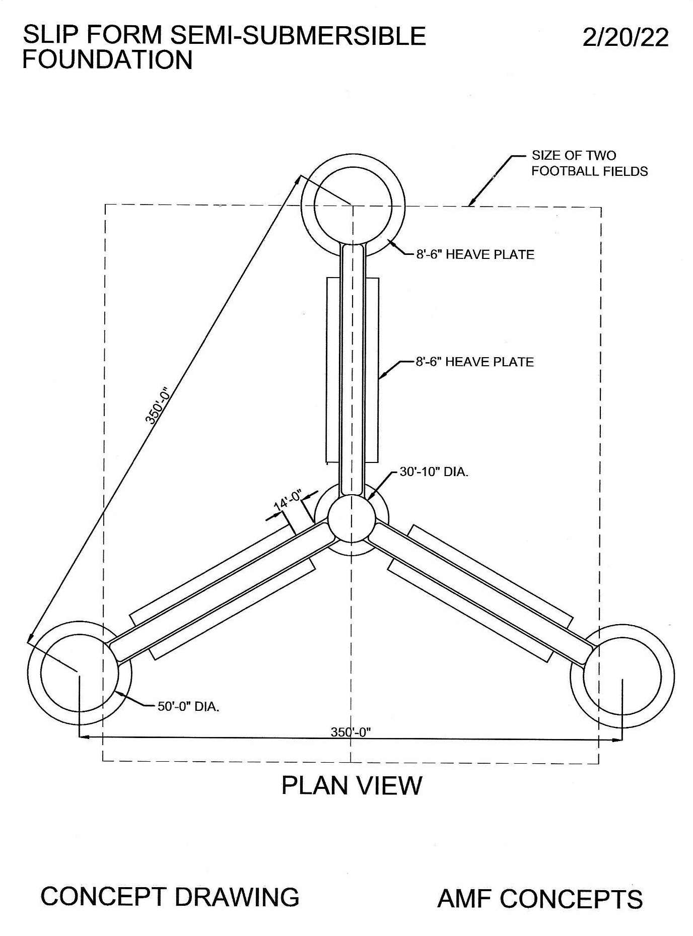
Wind-energy production far offshore will require innovative solutions to address challenging construction circumstances. U.S. naval architects and oil-and-gas engineering groups working on semi-submersible and spar buoy foundations certainly appreciate extreme sea conditions and have a clear design solution when it comes to addressing the yaw, roll, pitch, and heave of extreme sea states. Unfortunately, to assemble an effective semi-submersible foundation at scale would be incredibly cost-prohibitive, considering that the plan dimension of the structure is greater than two football fields (see Figure 1). In the past, lifting a 6-MW to 8-MW WTG nacelle onto a fixed-bottom foundation could be achieved with a crane barge, but the height and weight requirements of the new 18-MW to 20-MW WTG nacelles call for a crane ship, with a prohibitively costly day rate and an availability that could be restricted by other commitments or Jones Act requirements.
HISTORY INSPIRES A NEW LONG-LIVED MARINE CONCRETE
University labs and their material scientists, along with many private industry labs, have finally found the correct material and construction methods that work well for the offshore industry. Their search for a long-lived marine concrete took them to Rome, Italy, studying the volcanic ash and rock that made up historic concrete structures. The concrete dome of the Pantheon has withstood the test of time for more than 2,000 years, and the harbors outside of Rome include concrete breakwater structures footed deep in saltwater, which are estimated to be more than 1,000 years old.
Today, 100 percent of the concrete used in fixed-bottom and floating structures is made using ordinary portland cement (OPC). The OPC (binder) is the paste that holds traditional concrete together, but it has deficiencies when used in marine environments. Sodium, sulfates, and chloride compounds in sea water directly attack the calcium components of OPC, and this chemical reaction essentially rots the concrete.
A new high strength material called cold fusion concrete (CFC), is the solution. This CFC material was developed by Geopolymer Solutions around proprietary geopolymer concrete technology. This geopolymer binder contains as little as 2 percent calcium and is instead made up of inexpensive and widely available ingredients including alumino-silicates, fly ash, granulated ground blast furnace slag (GGBFS), zeolites, and water glass (anhydrous sodium metasilicate). The advantages of CFC are concentrated around durability and strength. CFC contains no OPC and, instead, is a dry cementitious material activated with water rather than chemical-liquid activators. The extremely low permeability and high strength of CFC produces a material with a lifespan in sea water, which will be measured in millennia rather than decades and centuries. The CFC materials, when produced and applied correctly, become the most durable material available in the construction industry.
Its CFC chemistry is unequivocally superior, producing a binder that requires no air entrainment or placement vibration ( self-consolidating) to achieve its strength.
The environmental sustainability of this product is further enhanced by the fact there is a 90 percent reduction in the carbon footprint associated with production of CFC compared to OPC. The curing of CFC can be performed conventionally or with low-voltage electrical current that expedites the strength accumulation and further reduces the carbon footprint.
LIGHTER WEIGHT AND STRONGER REBAR REINFORCEMENT
When selecting reinforcement materials to complement CFC, a nonmetallic rebar made from readily available basalt stone is the substance of choice. Basalt (generic solidified volcanic rock) is found all over the Earth and is a key component of the mix, enhancing the durability of the structure.
When heated to a temperature of approximately 1,500°C (2,730°F), basalt liquefies and can be extruded through a palladium die to produce soft, flexible threads. The threads are laid in parallel and locked together with epoxy to produce basalt rebar — a waterproof, chemically resistant, fireproof material with a tensile strength three times stronger than steel rebar. Compared to a similar diameter steel rebar, basalt rebar is seven to nine times lighter, but of equal strength.
Basalt fiber, much like nylon fiber, is chopped into variable lengths and used in the mix design for added strength. The CFC geopolymer binds to the basalt on a chemical level, in addition to mechanical bonding, further enhancing the structural integrity. For an offshore wind farm, the basalt bars are produced and bent in a portable construction plant in the back harbor. This facility also serves as the location for the slip forming of the tower component for the WTG, including the efficient installation of the tower internals.
BENEFITS OF SLIP-FORM CONSTRUCTION
Traditional metal structures require cutting, bending, welding, and costly handling to build a component. A new proposed construction technology, slip forming using CFC eliminates all of this and can produce the same strength requirement faster, at less cost, and with a longer lifespan. Slip forming is the continuous pouring of concrete into a form that is creating the product. When using CFC, slip forming enables nonstop, cast-in-place production of concrete structures with no cold joints.
Slip forming has a superior performance to jump-forming and other formwork systems by using unique discrete form elements. This slip-forming application relies on both the workability and quick-setting properties of the CFC concrete. The concrete needs to be workable enough to flow into the form and set up quickly enough to emerge from the form with a high degree of structural integrity and strength. This strength is paramount since the freshly set concrete must permit the formwork to slip past it without disturbance while also supporting the downward pressure of the new concrete being continually placed.
INNOVATIVE DOWN-SLIPFORM TECHNOLOGY
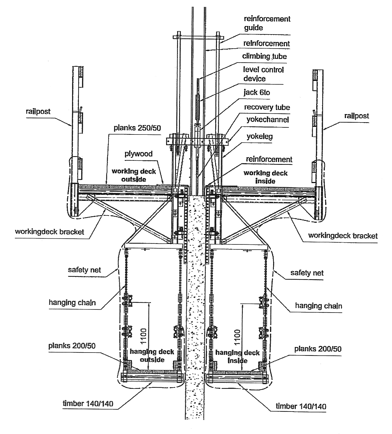
In traditional slip forming, the structure being formed is being created upward. To produce concrete infrastructures large enough to support an 18-MW to 20-MW direct-drive wind-turbine generator (WTG), the structures will have to be created going downward. As the continuous pour of the CFC proceeds, the slip-forming process pushes the newly formed structure downward into the sea. This new construction method is initiated on a submersible dry-deck barge (DDB) and is then completed on a custom-built construction vessel outside the supply harbor at a sea depth greater than the length of the designed structure. The formwork assembly consists of two work decks — a lower one for placing both the concrete and horizontal basalt rebar into the slip formwork and an upper deck to feed down the vertical basalt rebar and direct the placement of the concrete boom’s trunk. The entire work-deck assembly and formwork are raised as a single unit using hydraulic jacks, which climb steel pipes embedded in the cured concrete. When the slip is complete, these pipes are removed.
The down-slip forming method for any CFC floating structure is achieved by using a closed-end hull bottom structure, referred to as the starter-hull base, to support the jack rod load as well as the downward pressure from the two deck slip-form assemblies. This starter-hull base will be formed with conventional steel formwork. The starter-hull base will be cast on the center plate of a submersible dry-deck barge (DDB). A custom-designed wood plate is positioned under the starter-hull base to absorb the crush weight of the accumulating weight. The hydraulic jacks raise the decks and formwork assembly at a rate that allows the CFC to achieve a controlled cure rate by the time the formwork is slipped off.
Once the down-slip forming is under way, the starter-hull-base is slipped to 60 feet and then stopped. A system of ballast tanks on the DDB is then flooded and the barge is sunk to an effective float-off depth. The starter-hull base is then floated off and moved into the aft well of the construction vessel where the down-slip forming will be restarted and continued until the structure reaches its design depth.
ACHIEVING A SLIP RATE OF ONE- TO FOUR-FEET PER HOUR
This is accomplished by several factors such as ensuring a longer life in the forming panels by applying a PVC coating, and assuring that all the vertical rebar is designed for pre-tied cages with plastic spacer wheels and guide alignment systems to ensure appropriate spacing. All bars will be tied with plastic clip rebar tie guns. Each of the pre-tied vertical cages will be lifted to the top work deck in cage-lifting racks. The cages will then be placed in vertical guide fixtures and lap-tied to the previous cage.
All vertical cages can be handled by one rod buster. What makes this possible is that the basalt rebar is three times stronger and eight times lighter, enabling use of a smaller bar. Another factor is that CFC concrete will not require vibrating, which gives the inside and outside rod busters (placing and tying the horizontal bars through the yokes) more room to work.
The largest factor is the geopolymer CFC mix, which is designed to allow low-voltage electrical current to pass through the concrete to heat and accelerate the cure time. This electrically enhanced curing greatly expedites the slip process to achieve a down-slip-forming speed of one to four feet per hour, depending on the complexity of the pour, rather than the much slower six to eight inches per hour achieved when slip forming traditional ordinary portland cement.
This incredibly efficient down-slip-forming process results in previously unimaginable cost savings and accelerated time to market. Instead of 12 to 16 feet of conventional slip forming per 24-hour day, the down-slip forming process supports the production of 100 feet of structure per day (up to eight times faster).
SLIPFORM WORK DECK AND CONSTRUCTION VESSEL DECK ALIGNMENT
During the down-slip-forming process, the slip-forming work deck assembly will always be at an elevation to allow a member of the crew to step down onto the construction vessel’s main deck. This variable elevation is achieved by computer software that controls a measured water ballast placement in the hull while, at the same time, accounting for concrete placement, rebar, and crew weight.
The down-slip-formed structure is always floating free in the aft well of the construction vessel and is lightly supported by four tube-rollers. These rollers are equally spaced around the inside wall of the aft well. Each solid rubber roller is eight feet long, turning on a 10-foot long, 10-inch diameter stainless steel pipe. The rollers turn on sintered metal bearings allowing them to move laterally on the stainless-steel pipe. In an acceptable working sea state, dynamic positioning of the construction vessel via Azimuth thrusters will hold the well in position.
DOWN-SLIP FORMING THE SPAR BUOY FOUNDATION
The spar buoy floating foundation consists of cylindrical double -hull structure with an 80-foot outside diameter and a depth of 600 feet or more. After the aforementioned starter-hull-base is slipped off the dry-deck barge (DDB) and moved to the aft well of the construction vessel, the continuous down-slip forming resumes until the spar buoy structure reaches a depth of 600 feet.
When the spar buoy construction is complete, a large high-capacity pipe plug is placed on top of the buoy. The internal water ballast is then pumped out, allowing the spar buoy to float horizontally in preparation for tow out to the wind-farm site.
- Crews will work in three eight-hour shifts, 24 hours a day, to make up one workday.
- To pour, cast, and strip the starter-hull formwork on the dry-deck barge (DDB) will require one workday.
- Placing the double-deck slip formwork on the starter-hull will take two workdays.
- Floating off the starter hull from the DDB will require one workday.
- Moving the starter-hull into the production well of the construction vessel, restarting the slip, and continuing the down-slip forming to its completion at a 600-foot hull depth will require six workdays (deeper hull depths scale linearly in time, so an 800-foot hull depth would require eight workdays).
- Placement of the high-capacity pipe plug in the top of the spar buoy and pumping out the water ballast to achieve a horizontal float requires one workday.
- Total construction time for a 600-foot spar buoy floating foundation is just 11 workdays.
The innovative design of the spar buoy foundation includes an integrated system that allows the tower, nacelle, hub, and blades to be self-erecting, eliminating the need for an expensive crane ship.
DOWN-SLIP FORMING THE SEMI-SUBMERSIBLE FOUNDATION
The semi-submersible foundation (SSF) is a triangular structure with a pontoon affixed to each of the three points of the triangle. The direct-drive wind-turbine generator (WTG) and blade-support tower are normally placed in the center of the triangle, although this tower can have other placements such as the center point of one of each of the sides or on top of one of the three pontoons. The SSF concept described here is designed to support an 18-MW to 20-MW WTG. (See Figure 2)
The SSF consists of seven make-up components and all can be constructed using the down-slip-forming method described earlier. These components include three pontoons, three floating struts, and one tower WTG support structure. All components are designed to be assembled and connected while floating in water using a cold fusion concrete welding process to form a weldment. The individual components have a six-inch void on each end, and when joined with another component, the one-foot juncture allows for more CFC to be added. Since CFC bonds to itself, no cold joint is created, and the resulting bond is stronger than the individual components.
The total build-out time for this complete semi-submersible concrete foundation (not including the tower) is just eight 24-hour workdays.
In addition to the cost savings associated with such a short construction and assembly period, the SSF can be constructed without the added expense of a crane ship. However, unlike the spar buoy floating foundation, once the SSF foundation is completed, a crane ship is necessary to assemble and install the nacelle and blades of an 18-MW to 20-MW WTG at sea.
ZERO MAINTENANCE REQUIRED ON THE FLOATING FOUNDATIONS AND TOWERS
Some of the highest long-term cost drivers in deep water far offshore wind farms are crew transportation and farm maintenance. Boats with catamaran hulls will be required to transport crews safely and quickly in higher sea states, and these vessels are costly to purchase and operate.
The nacelle, hub, and blades of the WTG require routine maintenance, but the CFC semi-submersible and spar buoy floating foundations described, as well as the CFC tower structures for the WTGs, have been designed with materials that contain zero steel and will be maintenance-free for a millennium.
Using CFC floating foundations greatly reduces the total number of trips required to maintain the wind farm.
LONG LASTING STATION KEEPING ANCHORS
Since there is a wide range of sea floor conditions at the extreme depths of a far-offshore wind farm, only two anchor systems are recommended for use at these depths. The first system is a CFC chain or gravity anchor with a link length of eight feet and a link thickness of a foot and a half. This gravity anchor is constructed in a back-harbor construction plant using conventional steel formwork.
The second system is a CFC suction caisson anchor. The caisson anchor is an open bottom tube sealed at the top and embedded by suction in the sea floor. This caisson anchor can be down-slipformed at sea.
After the tube is formed, a high-capacity pipe plug is inserted on one end, the internal water is pumped out, and the anchor can be towed to the desired site. This anchor is quicker to install and remove than other methods and can handle multiple mooring lines.
Using CFC materials for these anchors not only extends their lifespans to a millennium, but it will reduce the capital cost associated with traditional mooring and anchoring.
SUMMATION
- The CFC concrete floating foundations, anchors, and towers to support a WTG of up to 20 MW or more will need no maintenance or replacement for a millennium.
- An independent cost opinion revealed that the production systems and materials chosen for these floating foundations will reduce the cost by a minimum of 40 percent.
- The CFC concrete semi-submersible and spar buoy floating foundations can be constructed and assembled in the water without the added expense of a crane ship and without expensive harbor real estate.
- The CFC concrete spar buoy construction design includes an integrated method to set its own tower, nacelle, hub, and blades — without the use of a crane ship.
* For other relevant articles previously published in Wind Systems see “The Greening of Offshore Wind Farm Construction” (December 2021) and “Elevating Hub Heights of Offshore WTGs Without Elevating Cost” (August 2021).


