


To lower the levelized cost of electricity (LCOE) generated by wind energy, the next generation of wind-turbine foundation solutions should be optimized to reduce the design and construction costs of wind turbines. These advanced foundation solutions help fill the gap following reduction in the production tax credit (PTC) benefits and lower capital expense for the power system construction.
Reducing Costs
Over the last decade, wind-energy pricing has declined by 70 percent, which is a remarkable achievement. However, wind must now compete with its renewable cousin, utility-scale solar, which has achieved a cost profile comparable to that of existing natural gas generation. P&H foundations are a strategy key to lowering the capital cost requirement of wind projects, which in turn, will better position wind power in a highly competitive market.
Patrick & Henderson (P&H) soil- and rock-anchor foundations and the Collar-P&H tensionless pier (CPHTP) foundations are the next generation of wind-turbine foundations. There is a P&H solution for most every onshore wind project, providing construction cost savings with superior long-term performance. The cost of utility-scale wind projects is about $2 million per turbine installed. The turbine foundation accounts for approximately 17 percent of the cost, so the cost savings of P&H foundations are a significant positive impact for the project.
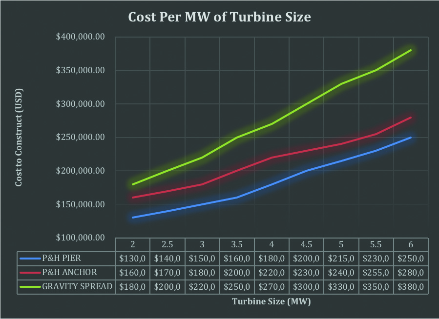
Compared to the gravity spread foot wind turbine foundation, the CPHTP foundations require up to 70 percent less concrete and reduce earthwork related to excavation by up to 80 percent in the CPHTP. The savings are greater the larger the wind turbine generator, higher the tower, and longer the blades, all of which fit the current market trends. For example, the break point for meaningful cost savings of a P&H foundation compared to a spread foot is realized at a turbine size exceeding 2 MW. However, the savings in concrete alone for a 4.5-MW land-based application would be more than 325 cubic yards. Overall, these alternative foundation designs represent a savings of anywhere from $250,000 to $400,000 per foundation depending upon site conditions and turbine size. (Figure 1)
Site Compatibility
To consider the viability of a CPHTP foundation for a wind turbine, the first step is to assess the site compatibility. One of the foundations (Collar-P&H tensionless pier, rock anchor, or soil anchor) will be compatible in nearly all situations and will provide cost savings compared against the gravity spread foot foundation. Still, it is a “horses for courses” determination that is required to ensure the most appropriate option is selected.
This is simpler than it might seem. Two criteria must be met to verify compatibility for the CPHTP foundation. First, the depth of groundwater must be below the termination of the excavation. Second, soil conditions must be favorable, which means self-standing soils (minimal sloughing or caving when excavated). If these conditions cannot be met and the site exhibits weak, saturated or non-self-supported soil or rock that cannot be excavated, then one of the two anchor solutions will be more appropriate.
After the initial compatibility analysis, a more detailed design is initiated, which takes into consideration anticipated geohazards, grading and drainage plans, loading, and constructability and applies these as weighted factors to preliminary foundation design calculations.
Geotechnical Considerations
P&H foundations are not your grandmother’s foundation. The geotechnical investigation for design considerations requires specific applications. Geotechnical exploration should include in-situ test methods to obtain direct measurements of the foundation soil’s stiffness and shear strength parameters. Typically, vane shear testing or cone penetration test with pore water pressure measurement (CPTu) is performed in saturated cohesive soils. In the case of highly dense soils and rock, soil/rock pressure meter testing should be performed.
Laboratory testing of the samples obtained during the characterization should include isotopically consolidated undrained tri-axial tests with excess pore water pressure measurement and constant rate-of-strain (CRS) tests for fine-grain soils. Slake durability tests should be performed for shales and other clay-bearing rocks, and in-situ permeability should be determined for any rock mass.
Ultimately, the geotechnical engineer will divide the area into zones based on the subsurface profile from boring logs, soundings, in-situ test results, and laboratory test results. Then, geophysics comes into play for confirmation of the previously designated zones. Using the multichannel analysis of surface waves (MASW) method or any other equivalent method, shear wave velocity and small-strain shear modulus profiles are obtained for each zone (typically three MASW readings per zone). The final assessment is produced in the form of a heat map that portrays locations in “green” as compatible, “yellow” as marginal, and “amber” as incompatible for the foundation option being considered. It is unlikely that the heat map will reveal that any of the P&H foundation types (CPHTP and P&H soil- and rock-anchor) will not be suitable for the site.
Theory and Design Attributes
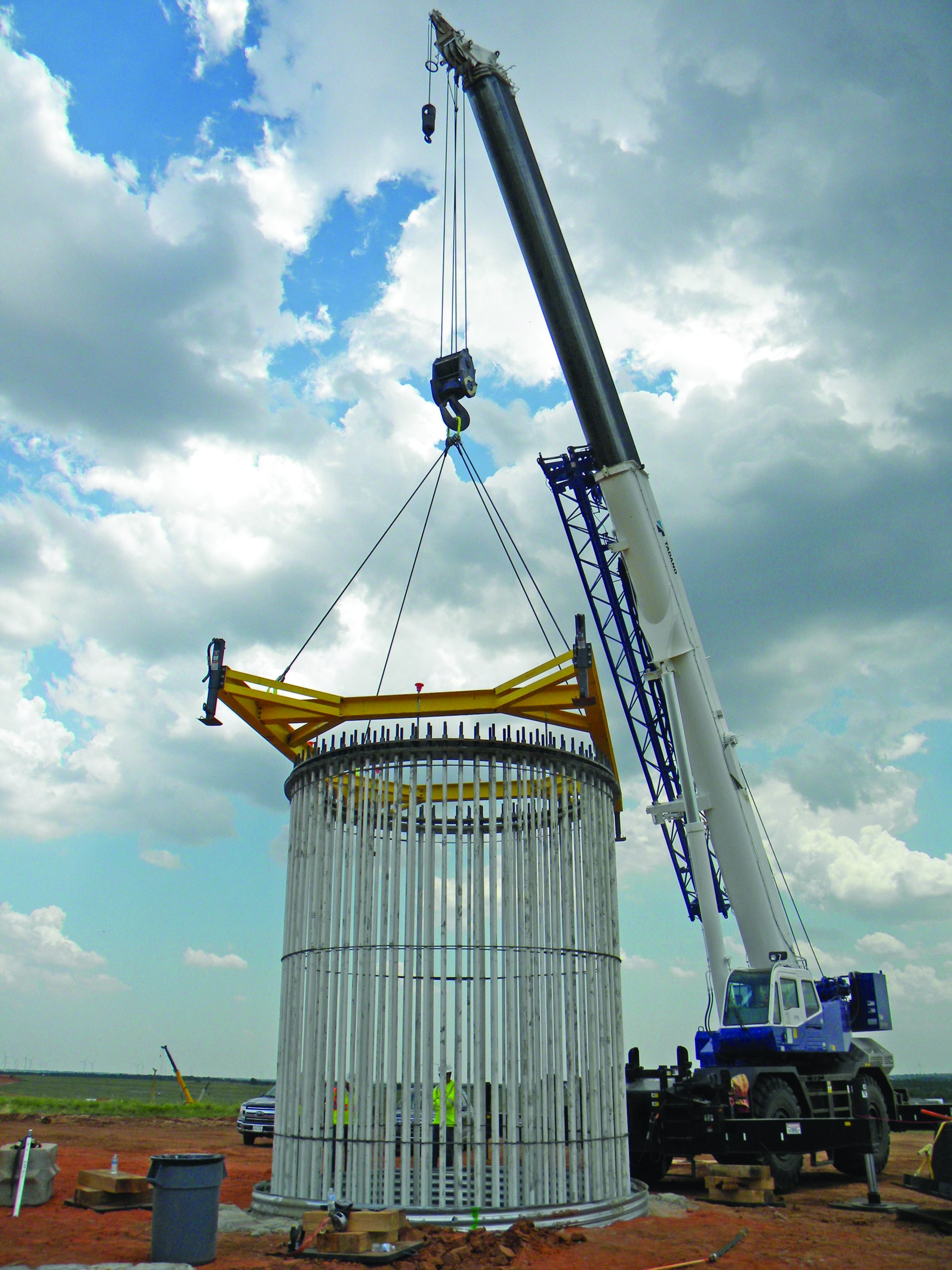
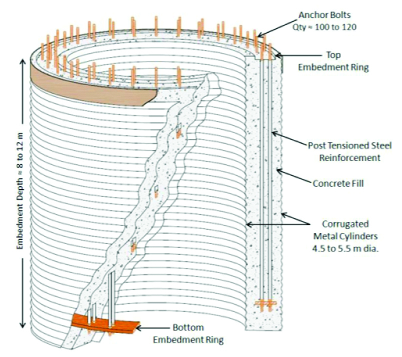
The most common application of P&H foundations is the CPHTP. This is an intermediate foundation system. The depth-to-length (D/L) ratio of the PHTP falls between the criteria for shallow and a deep foundation, and as such, cannot be categorized as either one. The response of the PHTP to the loading from the wind turbines is resisted through deformation of the foundation itself and the rigid body movement. The PHTP system configuration is basically a confined concrete mass between two corrugated shells; the confinement is achieved by prestressing the anchor bolts that go through the tower flange to an embedded ring at the bottom of the foundation. (Figure 2)
Structural concrete of the foundation is kept in compression through post tensioning of the anchor bolts. In general, this is a significant benefit over the spread-foot foundation, because it eliminates the need for costly structural steel and provides better response to fatigue loading. For any material with grain matrix, as the stresses remain in the compression side of the loading spectra, the damage due to small amplitude repetitive loading is minimized.
Design calculations for the PHTP foundation are performed using closed-form solutions and finite element simulations (FEM). The closed-form solutions rely upon assumptions, such as elastic half space, to predict the foundation response to loading. The FEM is performed by running simulations to predict the response of the foundation to various anticipated loading conditions.
Design calculations include two main components: geotechnical stability and internal structural analysis of the pier. The calculations goal is to ensure the existing P&H Pier foundations have an adequate factor of safety against global stability (a safety factor of two or greater) and meets serviceability requirements through providing adequate rotational stiffness and minimizing differential settlement to meet or exceed the turbine manufacturer requirements.
Design elements for P&H rock anchor and soil anchor are similar, relying upon a prestressed concrete cap and a grouted ground anchor soil or rock anchors. The pre-tensioning of the soil/rock anchors improves the subgrade under the cap by compression and provides adequate resistance to limit the movement of the cap and thus meets the global stability and serviceability requirements. The numerical simulations and closed-form solutions determine the depth, diameter, and quantity of the anchors.
Risk Reduction
Another advantage of the CPHTP is the inherent global stability. The geometry of the CPHTP will prevent possible catastrophic failure such as overturning, sliding, and bearing capacity. It is unlikely that driving moments will mobilize the passive wedge and overcome resisting moments from passive earth pressure above the rotation point of the rigid body.
The resistance for sliding is also resisted by the passive earth pressure, which will be significant, and it will satisfy the required safety factor. The diameter and depth of the PHTP will also ensure the development of sufficient axial capacity to resist vertical loading and prevent bearing capacity failures of the underlying material.
The CPHTP foundation solution is beneficial in seismically active areas because it provides a better seismic response than a gravity system foundation or deep foundations. The geometry of the PHTP and the flexibility will prevent rocking movement, and it will also provide enough resistance to the deformation as the seismic wave propagates.
In addition, in liquefiable soils, it is unlikely for the PHTP to be sheared by lateral spread due to the size of the foundation, the confinement from the CMPs, and the prestress in the anchors.
Another advantage is the foundation’s response to erosion and scouring. Significant issues have occurred on wind projects in or near foothills or mountainous areas such as Palm Springs and the Tehachapi areas of California that are prone to heavy episodic rains. Erosion events from extremely swift surface water flow have removed several feet of soil exposing and, in some cases, undermined gravity foundations. For the CPHTP the first two to four feet of the soil profile is intentionally replaced by a concrete collar.
Repowering Applications
Due to the geometry and relatively small diameter of these foundations (18 feet for the CPHTP and 30 feet for the anchor foundations) it is common to reuse the same foundation for a new larger wind turbine. Minimal and inexpensive modification are used for the addition of a supplemental collar. This extends the life of the original foundation and saves considerable time and expense.
Independent Review
These foundation systems have undergone favorable independent review by Sargent & Lundy and UL Renewables (formerly AWS Truepower). A basis of design review for the PHTP is being conducted by DNV-GL and is expected to be complete in early 2021.


