


In an ideal epicyclic gear set, every parallel gear path transmits the same amount of torque. However, it is well known that certain manufacturing variations result in unequal load sharing between the parallel gear paths. Previous works have developed and validated a general closed-form analytical model of this phenomenon that describes the load-sharing characteristics of epicyclic gear sets from three to six planets at any torque level. More recently, this analytical model has been reformulated to include the effects of gravity, carrier bearing clearance, and external applied moments, all of which are relevant to most gearboxes and their mounting configuration in horizontal-axis wind turbines. In this article, the reformulated model is compared to load measurements collected from two similar wind-turbine gearboxes with three-planet epicyclic gear sets. The resulting load-sharing values are also compared to the mesh load factor requirements in the AGMA 6006 and IEC 61400-4 wind-turbine gearbox design standards.
Load-sharing factors as high as 1.16 at extreme rotor moments and 1.08 with no moment were measured for the gearbox with cylindrical roller bearings, but the load-sharing factor remained below 1.10 for the gearbox with tapered roller bearings. Parametric studies of reducing the planetary system mass and carrier bearing clearance, even by modest amounts, resulted in an improvement in the load-sharing factor. The results show that in the wind-turbine application, load sharing is not equal — even for three-planet systems with a floating central member because of the effects of gravity, rotor moments, and the resulting relative motions among the epicyclic gear components within the carrier bearing clearance.
1 Introduction
Epicyclic gear sets have a number of identical gears, typically called planets, equally or nearly equally spaced on a carrier. They use the symmetry of the planet spacing to split input torque into multiple parallel paths, with each planet ideally carrying an equal portion of the input torque. It is well known that equal loading is not always achieved in practice because of manufacturing and assembly errors, such as carrier pin position error, variation in planet size, and runout of the gears [1]. The degree of inequality in load sharing has major implications for gear system sizing and rating, and the sensitivity to positional errors increases with the number of planets [2]. The effect of these errors on load sharing is accounted for in the design process by the planetary mesh load factor [3, 4], herein called the load-sharing factor.
Floating a central member in epicyclic systems improves planetary load sharing compared to fixed epicyclic systems [5, 6] and, generally, it can achieve equal load sharing for systems with three equally spaced planets [2].
The input stage of many wind-turbine gearboxes uses a three-planet, floating epicyclic configuration, intended to achieve nearly equal load sharing between the planets. However, these gearboxes are often mounted horizontally and in a so-called “three-point” configuration, such that the epicyclic system is subject to not only the rotor torque but also radial loads from gravity and rotor moments [7]. In controlled experiments, load-sharing factors as high as 1.15 for a planet gear and 1.46 for each individual bearing row supporting the planet gear have been measured [8]. Finite-element analyses have shown the unequal load sharing is a combined effect of the rotor moments, gravity, and the contact state of the carrier bearings relative to their clearances, rather than manufacturing errors [8][9].
A general, closed-form analytical model was previously formulated to estimate load sharing considering positional errors for three- to seven-planet epicyclic gear sets and was validated with finite-element analyses [2, 10]. However, this formulation did not consider the additional radial loads on typical wind-turbine gearboxes and their effect on load sharing when combined with clearance in the carrier bearings. This model has recently been reformulated to consider these effects without positional errors [11]. In this article, the reformulated model is validated with the measurements acquired from the previously conducted controlled experiments of two wind-turbine gearboxes with different carrier bearing clearances [8].
2 Experiments and Instrumentation
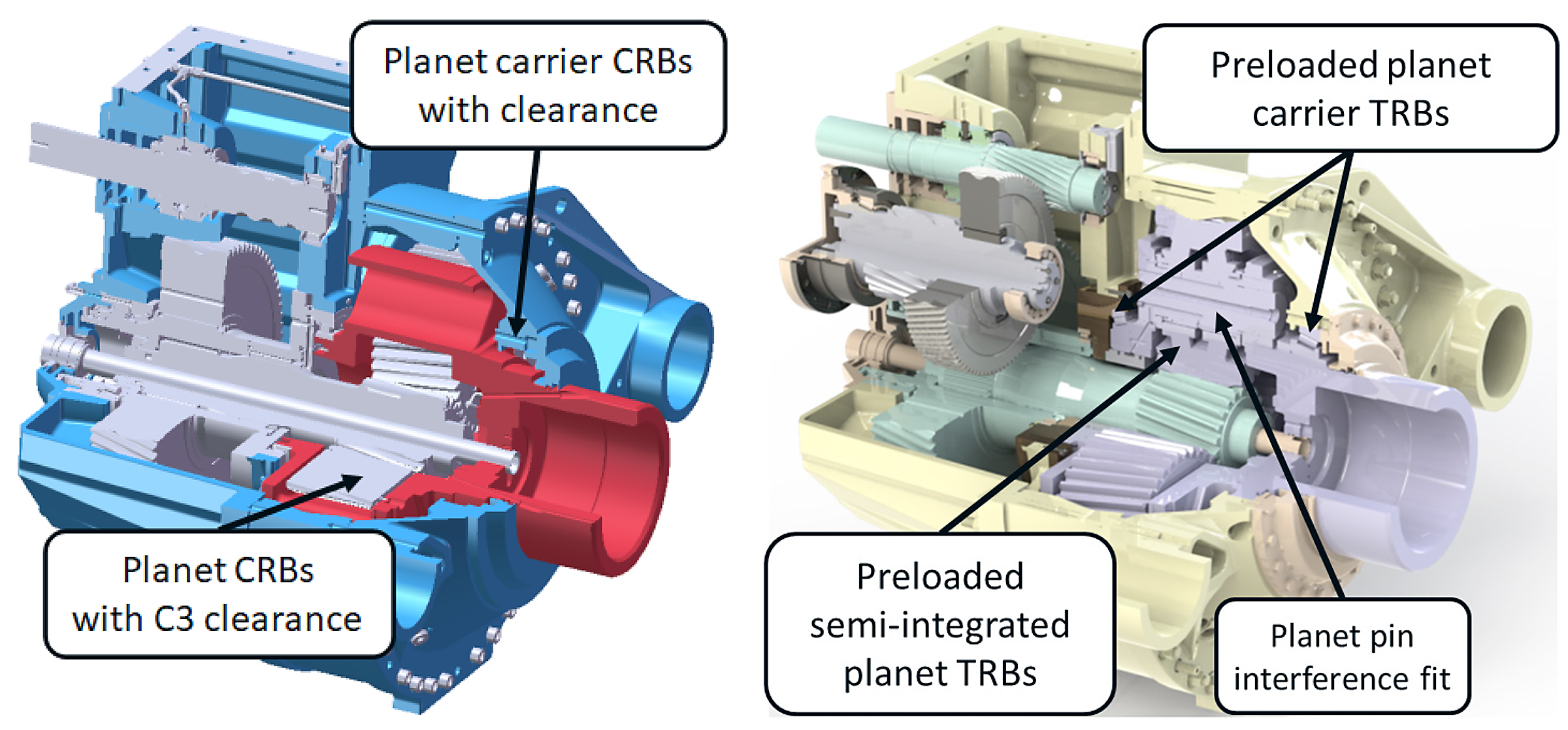
Experimental measurements of load sharing acquired from a repurposed NEG Micon 750-kilowatt (kW) wind-turbine drivetrain featuring a three-stage gearbox in a three-point mounting configuration, representative of most utility-scale drivetrain architectures, were used to validate the reformulated model. The two torque arms of the gearbox and the main bearing provide the three points of mounting support. The three-point mounted configuration transfers torque as well as rotor moments through the gearbox to the bedplate. For this work, the original Jahnel-Kestermann PSC 1000-48/60 gearbox, consisting of a single planetary input stage with three equally spaced planet gears followed by two parallel-shaft stages, was redesigned. The redesign features a planetary stage with new bearings and a sun pinion floated with a splined connection to a hollow shaft. Two different planetary section bearing configurations were designed and built in separate gearboxes. One featured cylindrical roller bearings operating in C3 clearance for the planets and CN-like clearance for the carrier, while the other featured tapered roller bearings under preload, as shown in Figure 1. Other than these planetary system differences and slight differences in gear-tooth microgeometry, the gearbox designs are nearly identical because each uses the same front and rear housing components and intermediate- and high-speed stage gearing [8].
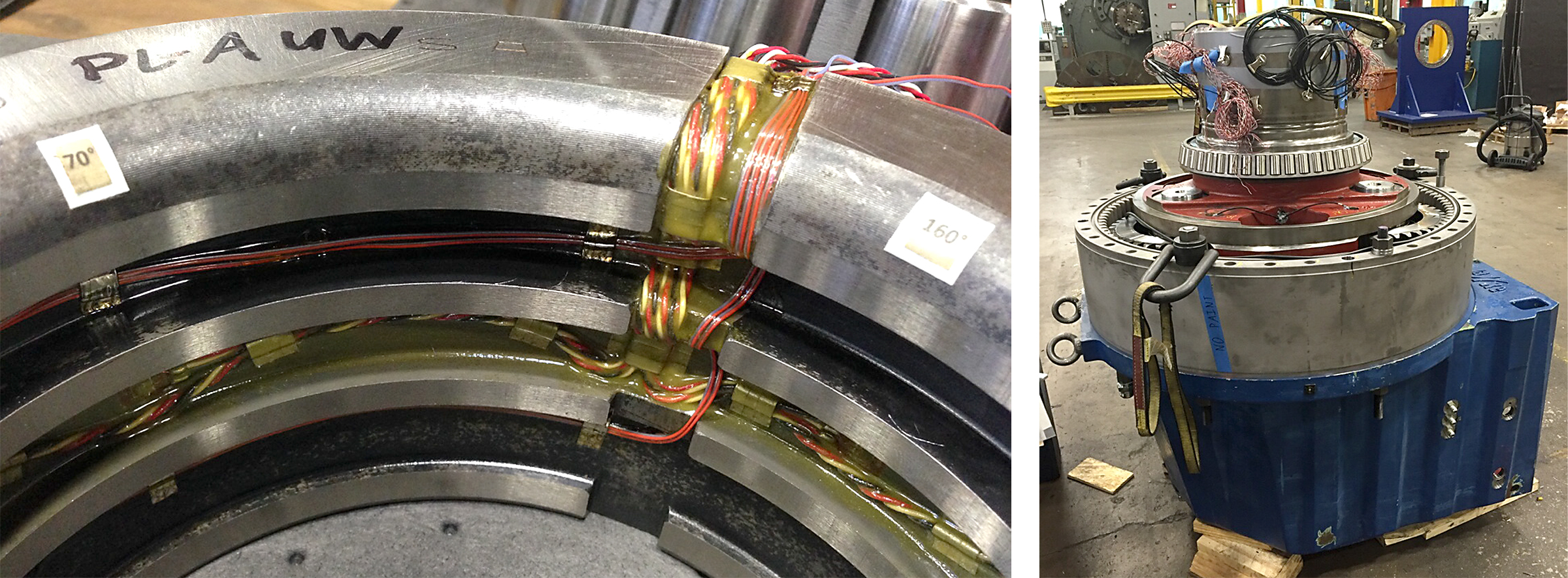
Instrumentation in the planetary gear stage focused on planet-bearing load-sharing characteristics. Thirty- six strain gauge pairs, mostly within the expected bearing load zones, were evenly placed between the upwind and downwind planet-bearing rows in each gearbox, as shown in Figure 2. The roller load at each location was determined by converting the average, measured strain range with calibration factors determined from dedicated bench experiments in a load press and assuming dynamic effects are small [12, 13]. The load-sharing factor was then calculated from the measured planet-bearing loads [8].
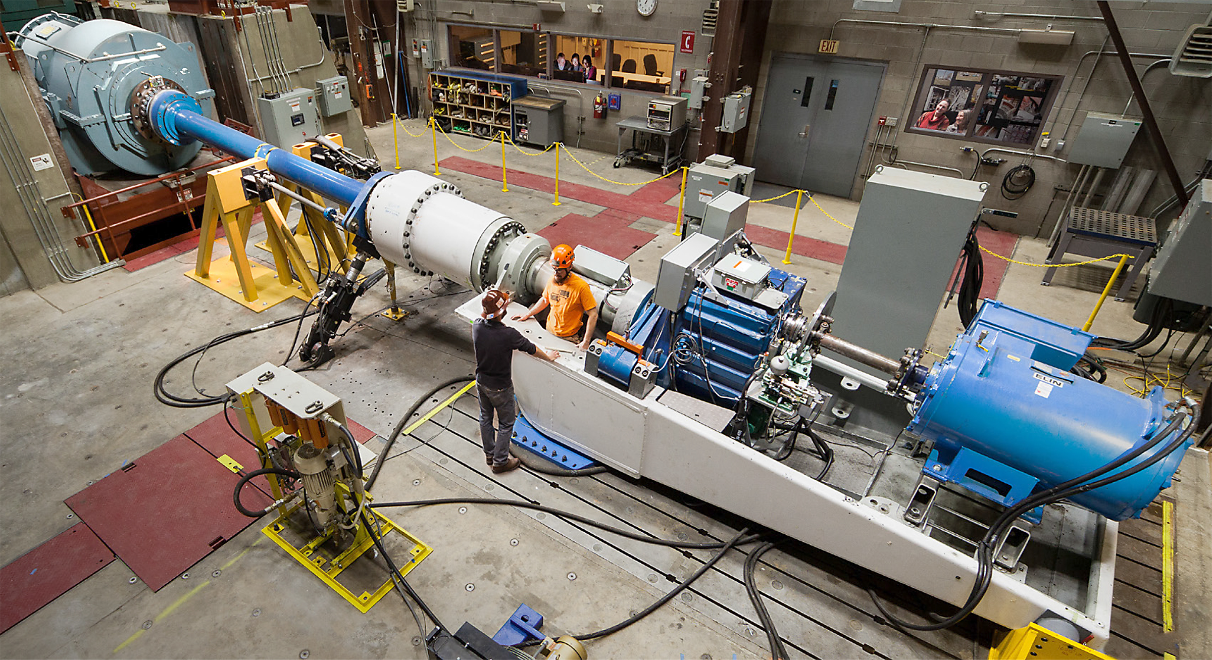
The drivetrain experiments were conducted in a dynamometer at the National Wind Technology Center, as shown in Figure 3. Steady-state operations were conducted at a rated speed of 22.1 revolutions per minute (rpm) for the rotor and 1,800 rpm for the generator from offline (i.e., generator disconnected) conditions to the rated electrical power of 750 kW and 325 kilonewton meter (kNm) mechanical torque [14, 15]. Representative rotor moments up to ±300 kNm as measured on the main shaft, based on field experiment results [16], were applied with hydraulic actuators to the adapter shaft connecting the dynamometer gearbox to the main shaft of the drivetrain.
3 Analytical Model
The free-body diagram of a three-planet epicyclic system, shown in Figure 4, is used to develop the reformulated analytical model. The applied torque, T, results in radial and tangential in-plane loads, Fr,t, on each planet gear, i. As described earlier, gearboxes mounted in three-point horizontal-axis wind turbines are subject to additional radial loads to the planetary gear set beyond that of the transmitted torque. These additional loads consist of the total gravity load from the planetary system and main shaft, mg, plus external loads, Fex, resulting from the weight moment of the rotor about the main bearing and aerodynamic moments. The carrier and planet bearings can share these loads, depending on their relative clearances. The reformulated analytic model [11] describes the additional forces in the wind-turbine application and the carrier bearing reaction forces, Fcr, the portion of the loads that can be compensated for by system float, and the required torque to bring each planet gear into contact in aprocess similar to previous work that accounted for positional errors [2].
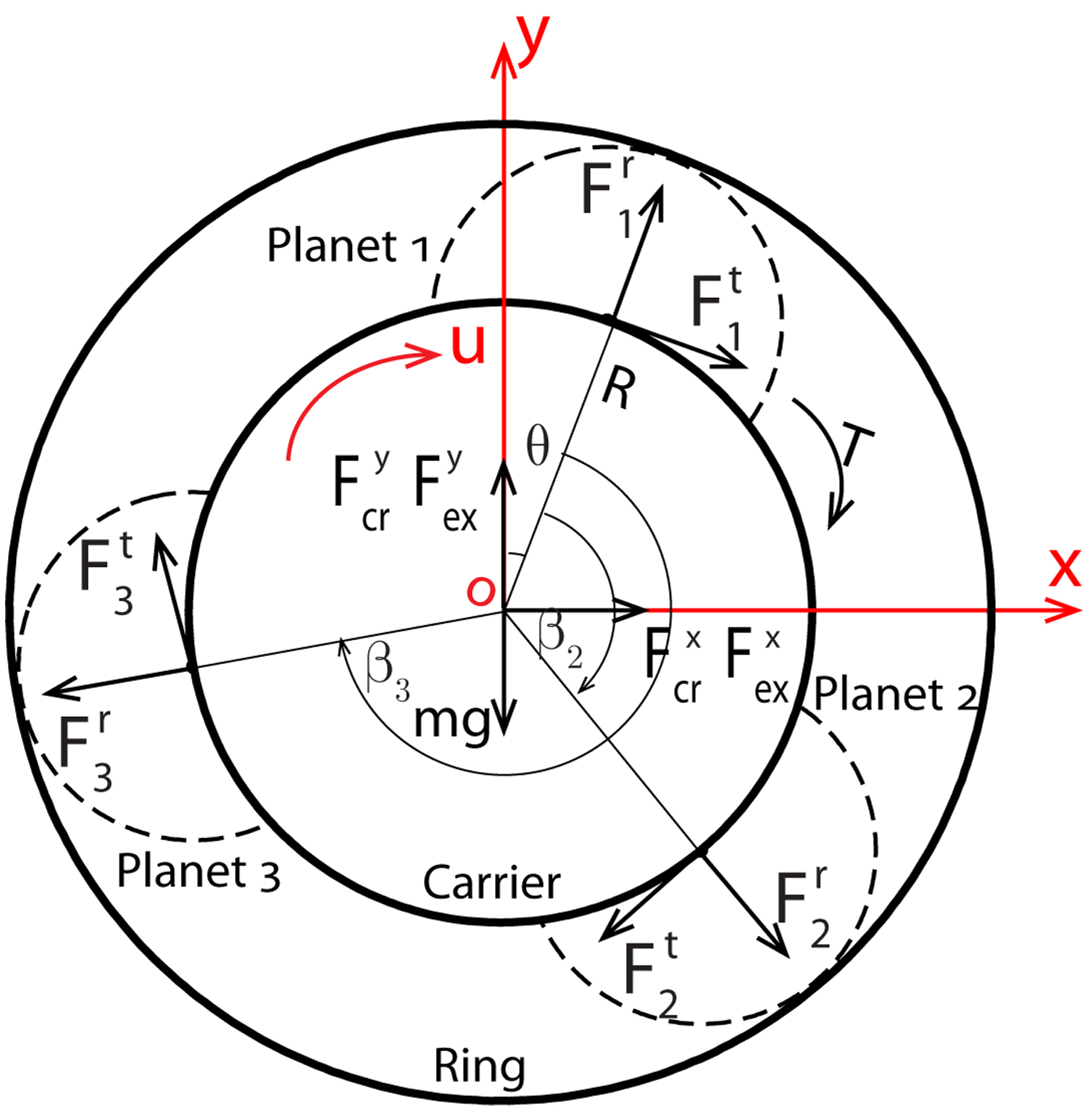
For a system with three equally spaced planets and sufficient floating, the tangential forces on each planet gear are:
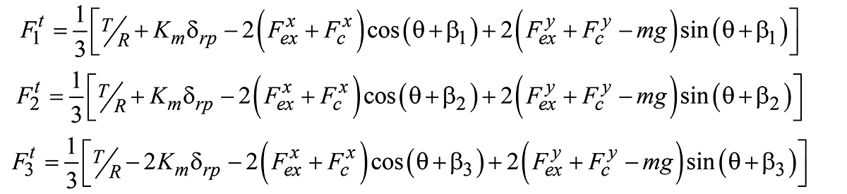 where
where
Fit are the tangential forces on each planet, i = 1,2,3.
T is the input torque.
R is the distance between the centers of the sun and planets.
Km is the equivalent planetary stiffness from the ring-planet gear
mesh, Krp , and planet bearing, Kb.
δrp is the carrier radial motion resulting from gravity and the
external rotor moments with respect to the equivalent planetary stiffness, carrier bearing stiffness, Kc , and carrier bearing clearance, Δc .
Fexx,y are the lateral, x, and vertical, y, forces resulting from the
external rotor moments.
Fcrx,y are the carrier bearing reaction forces.
mg is the equivalent weight of the planetary section and the main
shaft.
βi is the relative position of each planet, βi = 0, π/3, 2π/3 .
θ is the rotational position of the carrier from the vertical axis.
Although the carrier is typically supported by two bearings on either side of the planets, this formulation assumes there is a single carrier bearing reaction force, Fcr, acting at the center of the planets. The carrier bearing reaction force depends on the gear and bearing stiffnesses, carrier bearing clearance, and ring gear backlash [11]. The forces applied to the planetary system from the rotor moments are:
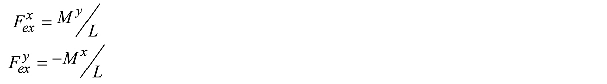 where
where
My,x are the rotor yaw and pitch moments, respectively.
L is the distance between the main bearing and the planets.
The constant gravity load and forces resulting from the rotor moments in Equations 1 and 2 cause a once-per-revolution sinusoidal variation in the planet forces [8, 9].
The vector summation of the planet forces can be expressed in terms of a non-dimensional load-sharing factor by dividing by the forces due to torque alone. For a system with three equally spaced planets and sufficient floating and assuming the planet radial forces, Fr, are small compared to the planet tangential loads, Ft, the load-sharing factor is:
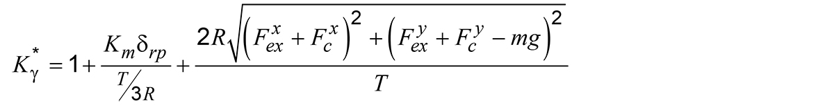 where
where
Kγ* is the maximum value of the mesh load factor over the carrier
rotation, Kγ* = | Kγ(θ) | [9].
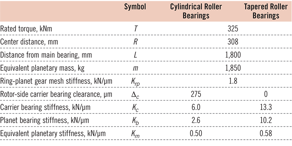
A load-sharing factor with a value of 1.0 indicates the planets are carrying the expected torque load, while values greater than 1.0 indicate the planets are carrying more load because of the additional forces in the wind-turbine gearbox application or because of positional errors [2]. Key design parameters necessary to calculate the load-sharing factor using the reformulated analytical model are listed in Table 1 for the gearboxes in this study. Although the tapered roller bearings are preloaded [8], the reformulated analytical model simply assumes they have zero clearance.
4 Results and Discussion
In this section, the reformulated analytical model is applied to the two gearbox designs and compared to the measurements of planet-bearing loads acquired during the dynamometer experiments, as shown in Figure 5. The load-sharing factor has distinct behaviors for each gearbox and whether rotor pitch or yaw moments were applied. In general, though, the load-sharing factor increases with increasing moment, as expected, for both gearboxes. The load-sharing factor is also lower for the gearbox with tapered roller bearings in the planetary system than the gearbox with cylindrical roller bearings.
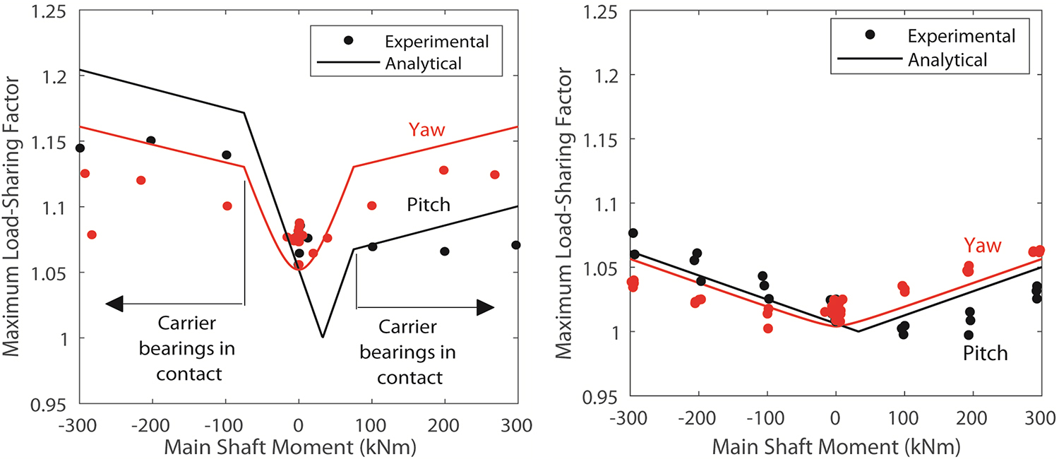
The most striking load-sharing behavior is for the gearbox with cylindrical roller bearings. With no applied moment, the load-sharing factor is 1.05 because much of the weight of the planetary section and main shaft is supported by the planet bearings. When subjected to small positive pitch moments, the load-sharing factor actually decreases and is predicted to reach the expected value of 1.0 at 33 kNm. This is the pitch moment required to relieve the equivalent weight from the planetary section and main shaft about the distance from the main bearing. As the pitch moment increases beyond this point, the load-sharing factor increases quickly to a value of approximately 1.07 at 75 kNm. In this condition, the carrier bearing has come into contact and is also supporting the pitch moment [8]. As the pitch moment increases even further, the planet loads do not increase as appreciably because the carrier bearings are also supporting the increased loads and the load-sharing factor only reaches 1.1. In contrast, as the pitch moment decreases below 33 kNm, the load-sharing factor quickly reaches higher values because of the additional gravity load on top of the loads resulting from the pitch moment. It reaches a value of 1.17 at minus-75 kNm, at which point the carrier bearings again become in contact, slowing from there and reaching a value of just more than 1.20 at minus-300 kNm. Yaw moments have a similar effect on the gearbox with cylindrical roller bearings as the pitch moments, with the load-sharing factor displaying a behavior that is symmetrical with positive or negative yaw moments. Within ±75 kNm, the carrier bearings are not in contact, and the planets support all the loads. Beyond this point, the carrier bearings react to the additional moments, and the load-sharing factor reaches 1.16. The reformulated analytical model predictions generally correspond to the experimental measurements, and, in many cases, the load-sharing factor is above the 1.10 design requirement in IEC 61400-4 [3] and AGMA 6006 [4]. The predictions are sensitive to the assumed carrier bearing clearance of 275 μm, which is difficult to determine accurately because the carrier bearings are a full complement and are affected by fits and bearing temperature. With low-rotor moments when the carrier bearings are either not in contact or only periodically in contact, the measured load-sharing factor is slightly higher than the model prediction.
For the gearbox with tapered roller bearings, load sharing is generally improved, and the predicted and measured load-sharing factors remain below 1.07 even at the highest pitch and yaw moments. Because the carrier bearings are always in contact, the load-sharing factor simply increases linearly for any pitch moment above the 33 kNm required to relieve the gravity load of the carrier and main shaft. With no rotor moment, the load-sharing factor is just above 1.0. For this gearbox, the experimental measurements always remain below the 1.10 design requirement. Both the carrier and planet bearings were designed to have some amount of preload, which tends to increase the planet loads slightly compared to the analytical model, which assumes no clearance or preload.
Figure 6 further examines the effect of the equivalent weight of the planetary section and main shaft by changing the mass of the system in the reformulated analytical model. Only pitch moment cases are displayed. For the gearbox with cylindrical roller bearings, as the equivalent mass is reduced, the behavior of the load-sharing factor becomes more symmetrical about the zero-applied moment and is reduced to a maximum value of 1.15 for the massless system. The point of the lowest load-sharing factor also moves closer to the zero-applied moment, indicating the weight of the system alone is responsible for any increase in the load-sharing factor above 1.0 at the zero-applied moment. The weight of the system has almost no effect on the load-sharing factor for the gearbox with tapered roller bearings, indicating the majority of the weight is always supported by the carrier bearing.
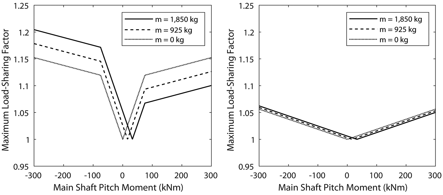
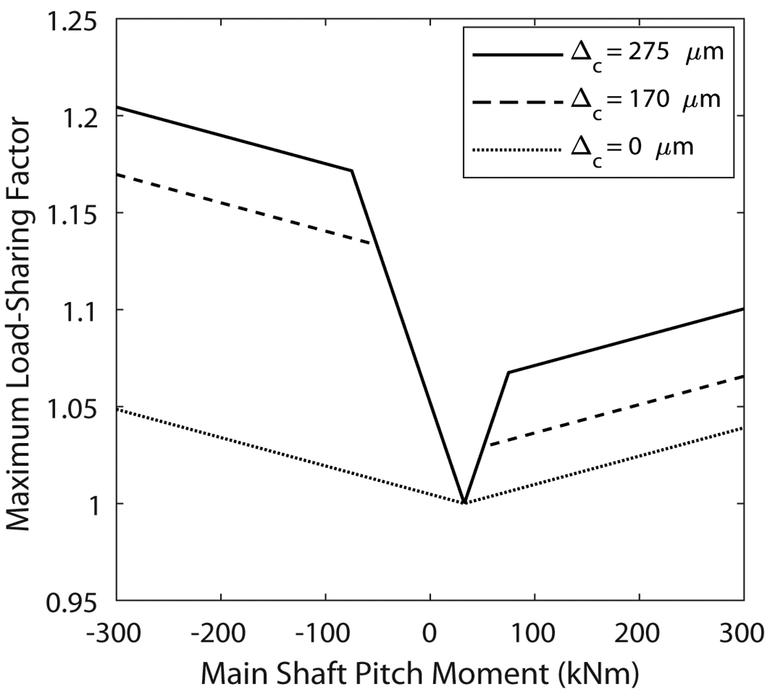
Figure 7 examines the effect of carrier bearing clearance on the load-sharing behavior of the gearbox with cylindrical roller bearings. Reducing the carrier bearing clearance from 275 μm to 170 μm results in a noticeable improvement in the load-sharing factor [8], but naturally only when the carrier bearing is in contact. There is no change in the load-sharing factor when the carrier bearing is operating in clearance. As the carrier bearing clearance is eliminated, the load-sharing factors approach the same values as for the gearbox with tapered roller bearings — the only relatively minor difference in the two systems being a result of the difference in stiffnesses of the planet and carrier bearings.
5 Conclusions
This article validates an analytical model for estimating load sharing of three-planet epicyclic gear sets that has been reformulated for wind-turbine gearboxes to consider the effects of gravity related to carrier bearing clearance and moments from the rotor. The predicted load-sharing factor was validated with experimental results for two different gearboxes, one supported by cylindrical roller bearings with clearance and another supported by tapered roller bearings with preload, that were studied in controlled dynamometer experiments. The reformulated analytical model was also used to examine the effect of gravity loads and different cylindrical roller bearing clearance settings in the carrier bearing.
For wind-turbine gearboxes with three planets, equal load sharing cannot be achieved in all cases by floating the central member. Load-sharing factors as high as 1.16 at extreme rotor moments, and even 1.08 with no moment, were measured for the gearbox with cylindrical roller bearings, but the load-sharing factor remained below the 1.10 design requirement in AGMA 6006 and IEC 61400-4 for the gearbox with tapered roller bearings. Reducing the equivalent mass of the planetary system and clearance in the carrier bearings, even by relatively small amounts, improves load sharing for gearboxes with cylindrical roller bearings.
6 Acknowledgements
This work was authored by the National Renewable Energy Laboratory, operated by Alliance for Sustainable Energy, LLC, for the U.S. Department of Energy (DOE) under Contract No. DE-AC36- 08GO28308. Funding provided by the U.S. Department of Energy Office of Energy Efficiency and Renewable Energy Wind Energy Technologies Office. The views expressed in the article do not necessarily represent the views of the DOE or the U.S. government. The U.S. government retains and the publisher, by accepting the article for publication, acknowledges that the U.S. government retains a nonexclusive, paid-up, irrevocable, worldwide license to publish or reproduce the published form of this work, or allow others to do so, for U.S. government purposes.
The authors would also like to thank Avinash Singh of General Motors for his contributions to this work.
Bibliography
- Bodas, A. and Kahraman, A., 2004, “Influence of Carrier and Gear Manufacturing Errors on the Static Load Sharing Behavior of Planetary Gear Sets,” JSME International Journal Series C Mechanical Systems, Machine Elements and Manufacturing, 47(3), pp.908-915.
- Singh, A., 2010, “Load Sharing Behavior in Epicyclic Gears: Physical Explanation and Generalized Formulation,” Mechanism and Machine Theory, 45(3), pp.511-530.
- IEC, 2012, “Wind turbines — Part 4: Design requirements for wind turbine gearboxes,” IEC 61400-4.
- AGMA, 2020, “Standard for the design and specification of gearboxes for wind turbines,” ANSI/AGMA 6006-B20.
- Hidaka, T. and Terauchi, Y., 1976, “Dynamic Behavior of Planetary Gear: 1st Report Load Distribution in Planetary Gear,” Bulletin of JSME, 19(132), pp.690-698.
- Singh, A., 2005, “Application of a System Level Model to Study the Planetary Load Sharing Behavior,” Journal of Mechanical Design, 127(3), pp.469-476.
- Guo, Y., Parsons, T., Dykes, K. and King, R. N., 2017, “A Systems Engineering Analysis of Three-Point and Four-Point Wind Turbine Drivetrain Configurations,” Wind Energy, 20(3), pp.537–-550.
- Keller, J., Guo, Y., Zhang, Z. and Lucas, D., 2018, “Comparision of Planetary Bearing Load-Sharing Characteristics in Wind Turbine Gearboxes,” Wind Energy Science, 3(2), pp.947-960.
- Guo, Y., Keller, J. and LaCava, W., 2015, “Planetary Gear Load Sharing of Wind Turbine Drivetrains Subjected to Non-torque Loads,” Wind Energy, 18(4), pp.757-768.
- Singh, A., 2011, “Epicyclic Load Sharing Map – Development and Validation,” Mechanism and Machine Theory, 46(5), pp.632-646.
- Guo, Y., Keller, J. and Singh, A., 2020, “Generalized Formulation for Load Sharing Behavior in Epicyclic Gears for Wind Turbines,” submitted to Mechanism and Machine Theory.
- van Dam, J., 2011, “Gearbox Reliability Collaborative Bearing Calibration,” NREL/TP-5000-47852, National Renewable Energy Laboratory, Golden, CO.
- Keller, J., 2017, “Gearbox Reliability Collaborative Gearbox 3 Planet Bearing Calibration,” NREL/TP- 5000-67370, National Renewable Energy Laboratory, Golden, CO.
- Keller, J. and Wallen, R., 2015, “Gearbox Reliability Collaborative Phase 3 Gearbox 2 Test Report,” NREL/TP-5000-63693, National Renewable Energy Laboratory, Golden, CO.
- Keller, J. and Wallen, R., 2017, “Gearbox Reliability Collaborative Phase 3 Gearbox 3 Test Report,” NREL/TP-5000-67612, National Renewable Energy Laboratory, Golden, CO.
- Link, H., LaCava, W., van Dam, J., McNiff, B., Sheng, S., Wallen, R., McDade, M., Lambert, S., Butterfield, S. and Oyague, F., 2011, “Gearbox Reliability Collaborative Project Report: Findings from Phase 1 and Phase 2 Testing,” NREL/TP-5000-51885, National Renewable Energy Laboratory, Golden, CO.
Printed with permission of the copyright holder, the American Gear Manufacturers Association, 1001 N. Fairfax Street, Suite 500, Alexandria, Virginia 22314. Statements presented in this paper are those of the authors and may not represent the position or opinion of the American Gear Manufacturers Association. (AGMA) This paper was presented October 2020 at the AGMA Fall Technical Meeting. 20FTM03


